Z-tangent LNOI electro-optical modulator capable of improving modulation efficiency and application thereof

An electro-optic modulator and modulation efficiency technology, applied in the field of integrated optics, can solve the problems of high power consumption of devices, high half-wave voltage, low electro-optic modulation efficiency, etc., to improve modulation bandwidth, reduce half-wave voltage, and high electro-optic efficiency. Effect

Active Publication Date: 2020-08-04
INST OF SEMICONDUCTORS - CHINESE ACAD OF SCI
View PDF9 Cites 6 Cited by
  • Summary
  • Abstract
  • Description
  • Claims
  • Application Information

AI Technical Summary

Problems solved by technology

The electrodes of traditional lithium niobate modulators mostly adopt the form of coplanar electrodes, and a large part of the electric field does not act on the optical field, resulting in low electro-optical modulation efficiency, high half-wave voltage, and high power consumption of the device

Method used


Image

  • Z-tangent LNOI electro-optical modulator capable of improving modulation efficiency and application thereof

Examples


Embodiment

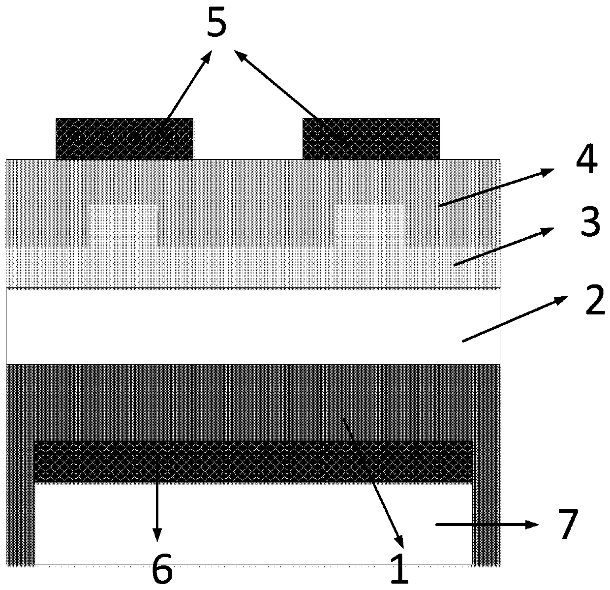
[0057] Such as figure 1As shown, this embodiment provides a Z-cut LNOI electro-optic modulator with high modulation efficiency, including a substrate 1 , an insulating layer 2 , a waveguide core layer 3 , an upper cladding layer 4 , a signal electrode 5 , a ground electrode 6 , and a slot 7 .

[0058] The upper surface of the substrate 1 is an insulating layer 2, and the upper surface of the insulating layer 2 is a LN film layer. Usually, the thickness of the ultra-thin film layer is less than 1 micron. The waveguide core layer 3 is prepared on the uppermost layer of the LN film. It can be made into a ridge or strip type, and then a certain thickness of the upper cladding 4 is deposited on the 3. The difference in refractive index between the waveguide core 3 and the upper cladding 4 is compared with that of niobic acid formed by traditional titanium diffusion or proton exchange. The refractive index difference of the lithium waveguide is about 70 to 80 times larger, so the li...


PUM

PropertyMeasurementUnit
thicknessaaaaaaaaaa
thicknessaaaaaaaaaa

Abstract

The invention relates to a Z-tangent LNOI electro-optical modulator capable of improving modulation efficiency and an application thereof. The Z-tangent LNOI electro-optical modulator comprises a substrate, an insulating layer, a waveguide core layer, an upper cladding layer, a signal electrode and a ground electrode, wherein a bottom of the substrate is provided with a groove; the insulating layer is disposed on the substrate; the waveguide core layer is arranged on the insulating layer, and a tangential direction of the waveguide core layer is Z-tangent; the upper cladding layer is arrangedon the waveguide core layer, is used for forming a refractive index difference with the waveguide core layer so as to limit transmission of an optical field, and is used as a support structure of an upper-layer electrode; the signal electrode is arranged at the position, corresponding to an optical waveguide, of the cladding layer and used for applying an electric signal to form an electric fieldto perform electro-optical modulation on light in the waveguide core layer; and the ground electrode is arranged in the groove, and an electric field between the ground electrode and the signal electrode is along an optical axis direction of the Z-tangent LN. In the invention, ultra-efficient electro-optical modulation of near 100% of the electric field to an optical field is realized so that a half-wave voltage of the modulator is greatly reduced, and power consumption of the modulator is reduced.

Description

technical field [0001] The invention belongs to the field of integrated optics, and more specifically relates to a Z-cut LNOI electro-optic modulator for improving modulation efficiency and its application. Background technique [0002] As one of the core devices in optical communication and optical interconnection systems, the modulator realizes the conversion of electrical signals to optical signals, and its performance directly determines the performance of the entire communication system. It is used in long-distance optical communication links, data centers, supercomputers, etc. In short-distance communication interconnection application scenarios, in addition to "high speed and large capacity", "miniaturization, integration and low loss" are also important requirements and development goals, so the development of easy-to-integrate, low-power, low-cost optoelectronic devices is There is an urgent need to facilitate the development of high-speed optical communication syst...

Claims


Application Information

Patent Timeline
Patent Type & Authority Applications(China)
IPC IPC(8): G02F1/03G02F1/035
CPCG02F1/0316G02F1/035
Inventor 李金野刘建国戴双兴李明轩赵奕儒
Owner INST OF SEMICONDUCTORS - CHINESE ACAD OF SCI
Why Eureka
Try Eureka