Automatic sand mold casting mold forming production line and method

A casting mold forming and production method technology, which is applied in the field of sand mold casting, can solve problems such as size and weight restrictions, unreasonable setting of sand cleaning devices, and inability to automatically clean sand for large workpieces, so as to achieve the effect of ensuring cleanliness and safety

Inactive Publication Date: 2020-08-07
烟台冰轮智能机械科技有限公司
View PDF8 Cites 4 Cited by
  • Summary
  • Abstract
  • Description
  • Claims
  • Application Information

AI Technical Summary

Problems solved by technology

Such an automatic production line has restrictions on the size and weight of workpieces, and the setting of the sand

Method used


Image

  • Automatic sand mold casting mold forming production line and method
  • Automatic sand mold casting mold forming production line and method
  • Automatic sand mold casting mold forming production line and method

Examples


Embodiment Construction

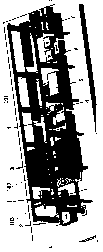
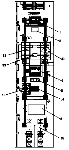
[0031] Such as figure 1 and figure 2 As shown, the automatic sand mold forming production line of the present invention includes a truss robot 1 , a feeding device 2 , a sand cleaning device 3 , a dipping device 4 , a drying device 5 and a core assembly device 6 . The core assembly device includes a core assembly platform 61 and a three-dimensional warehouse 62 .

[0032] Such as figure 1 As shown, two rows of columns 101 are set on both sides of the production line, slide rails 102 are installed on the columns 101, the truss robot 1 is installed on two parallel slide rails 102, and the truss robot 1 can slide along the slide rails 102, so that the truss robot 1 can move along the direction of the production line. The beam 103 installed between the two slide rails 102, the robot can move on the beam 103 in the direction perpendicular to the production line, so that the truss robot 1 can handle sand core workpieces of various shapes, which is more flexible than the gripper ...


PUM


Abstract

The invention relates to an automatic sand mold casting mold forming production line which comprises a truss robot, a feeding device, a sand removing device, a coating device, a drying device and a core assembling device. The truss robot is mounted on two parallel sliding rails, and can slide along the sliding rails, and the sliding rails are mounted on stand columns. The sand removing device comprises an automatic sand removing room, a manual sand removing room and a transferring trolley. The truss robot can place workpieces on the transferring trolley, and the transferring trolley can transfer the workpiece to the automatic sand removing room and the manual sand removing room. According to the automatic sand mold casting mold forming production line, unmanned operation can be achieved inthe whole process, the labor cost is reduced, rigid grabbing points do not need to be additionally arranged, and the demolding difficulty is reduced; the grabbing process and the like are high in repeated positioning precision, sand molds cannot be damaged, the sand core rejection rate is low, and all sand molds can be compatible; and due to the fact that sand mold production is mixed routing production, the time wasted by replacing fingers and other accessories is greatly shortened, and the production cost is reduced.

Description


Claims


Application Information

Patent Timeline
Owner 烟台冰轮智能机械科技有限公司
Why Eureka
Try Eureka