
Design method of continuous casting billet solidification tail end traveling wave electromagnetic stirring

A technology of solidification end and electromagnetic stirring, which is applied in the field of metal casting, can solve the problems of insufficient mixing of molten steel, lower performance of steel products, and dead zone in the center of billet, so as to improve center segregation, improve quality, and reduce center segregation Effect

Pending Publication Date: 2020-08-07
NORTHEASTERN UNIV
View PDF5 Cites 3 Cited by
  • Summary
  • Abstract
  • Description
  • Claims
  • Application Information

AI Technical Summary

Problems solved by technology

[0003] Since the solute changes with the solid phase ratio of the molten steel, the solute elements are continuously discharged from the solid phase to the liquid phase during the solidification process of the slab. At the end of the solidification, a large amount of solute gathers in the center of the slab to form a Center segregation, especially with the improvement of quality requirements in the production and application of continuous casting slabs, the increase of C solute in the center of the slab at the end of solidification can easily endanger the quality of steel and reduce the product performance of steel products
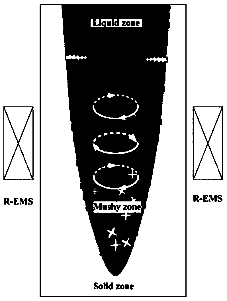
[0004] In order to improve the final quality of casting slabs, major steel mills mainly use such as figure 1 The rotary electromagnetic stirring at the solidification end is shown to reduce the center segregation, but the rotary electromagnetic stirring promotes the horizontal rotation of the molten steel, resulting in a dead zone in the center of the slab in the horizontal direction, which cannot fully mix the molten steel in the upper and lower parts of the slab. Uniform, limited improvement in central segregation

Method used


Image

  • Design method of continuous casting billet solidification tail end traveling wave electromagnetic stirring
  • Design method of continuous casting billet solidification tail end traveling wave electromagnetic stirring
  • Design method of continuous casting billet solidification tail end traveling wave electromagnetic stirring

Examples


Embodiment l

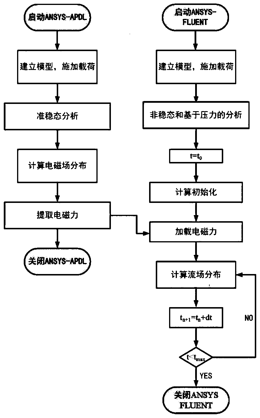
[0032] In this embodiment, a design method of traveling wave electromagnetic stirring at the end of continuous casting slab solidification, such as figure 2 shown, including the following steps:

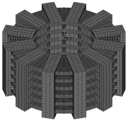
[0033] Step 1, using a traveling wave electromagnetic stirrer at the solidification end of the continuous casting slab, according to the size and parameters of the traveling wave electromagnetic stirrer, use the finite element analysis software ANSYS-APDL to establish a three-dimensional mathematical model of the traveling wave electromagnetic stirrer, as image 3 shown; wherein, the traveling wave electromagnetic stirrer parameters include current intensity, current frequency and coil turns; the mathematical model of the traveling wave electromagnetic stirrer includes iron core model, coil model, slab model and air model;

[0034] Step 1.1, load the finite element analysis software pre-processing module, define the magnetic field unit and set the coil turns, coil size, current inte...

Embodiment 2

[0050] In this embodiment, on the basis of the parameters of the casting machine and continuous casting in a steel plant, the streamline distribution of the longitudinal section of the molten steel of the billet is analyzed when a traveling wave electromagnetic stirrer is used at the end of solidification.

[0051] In this embodiment, the section diameter of the billet is 500 mm, and the casting speed of the continuous casting machine is 0.32 m / min. Table 1 below shows the physical parameters of the actually produced steel type 42CrMo steel.

[0052] Table 1 physical parameters of steel type 42CrMo steel

[0053]

[0054]

[0055] Step S1. First, determine the size of the initial traveling wave electromagnetic stirrer according to the process size of the continuous casting equipment in the steel plant, and use Gambit modeling software to establish a three-dimensional mathematical model of the traveling wave electromagnetic stirrer. The specific dimensions are shown in Tab...


PUM


Abstract

The invention provides a design method of continuous casting billet solidification tail end traveling wave electromagnetic stirring, and relates to the technical field of metal casting. The method comprises the steps: employing a traveling wave electromagnetic stirrer at the solidification tail end of a continuous casting billet, employing finite element analysis software for establishing a three-dimensional mathematical model of the traveling wave electromagnetic stirrer, and performing material attribute distribution and model networking on the model; loading a current to a coil in the model; setting boundary conditions to solve an electromagnetic force generated by a coil loading current, and extracting and displaying the electromagnetic force; interpolating the extracted electromagnetic force, importing the electromagnetic force into fluid calculation software, simulating the flowing of molten steel in the model, extracting streamline distribution on the longitudinal section of thecontinuous casting billet, obtaining the solute redistribution situation of the molten steel in the continuous casting solidification process, and then judging the center segregation situation of thecasting billet; finally, adjusting the parameters of the traveling wave electromagnetic stirrer, repeating simulation calculation, integrating the center segregation conditions of the casting blank under different parameters, and obtaining the optimal parameters of the traveling wave electromagnetic stirrer.

Description

technical field [0001] The invention relates to the technical field of metal casting, in particular to a design method for traveling wave electromagnetic stirring at the solidification end of continuous casting slabs. Background technique [0002] With the rapid development of the economy and the increasingly fierce market competition, the demand for high-quality steel materials required by the market is increasing day by day. Continuous casting billet products are widely used in the manufacture of major equipment in the fields of transportation, machinery manufacturing, petrochemical industry, wind power generation, etc., and have important strategic significance and economic value. With the continuous development of equipment manufacturing in the direction of large-scale and high-end, continuous casting billet products are also advancing in the direction of large cross-section and high performance. However, the problem of segregation at the center of the slab still needs ...

Claims


Application Information

Patent Timeline
IPC IPC(8): G06F30/23B22D11/115G06F111/10
CPCG06F30/23B22D11/115G06F2111/10
Inventor 罗森尹胜奎郭壮群王卫领朱苗勇
Owner NORTHEASTERN UNIV
Learn More