Bioremediation device for treating river pollution

A technology for bioremediation and river pollution, applied in biological treatment devices, polluted waterways/lakes/ponds/rivers, biological water/sewage treatment, etc. Problems such as water flow and limited length of plant roots can achieve the effect of convenient centralized treatment, avoiding secondary pollution, and improving decomposition speed

Inactive Publication Date: 2020-08-11
曹钰坤
View PDF8 Cites 2 Cited by
  • Summary
  • Abstract
  • Description
  • Claims
  • Application Information

AI Technical Summary

Problems solved by technology

[0003] However, planting plants alone to purify river water not only takes a long repair period, but also has limited root length, which cannot treat pollutants in deep water areas; in addition, conventional bioremediation devices can only treat pollutants in the river water at t

Method used


Image

  • Bioremediation device for treating river pollution
  • Bioremediation device for treating river pollution
  • Bioremediation device for treating river pollution

Examples


Embodiment 1

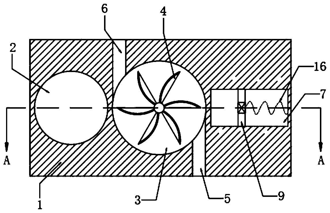
[0020] refer to Figure 1-2 , a bioremediation device for controlling river pollution, comprising a floating plate 1, the upper end of the floating plate 1 is provided with an aquatic plant placement groove 2, the side wall of the floating plate 1 is provided with a circular groove 3, and the inner surface of the circular groove 3 The bottom is rotatably connected with a water wheel 4. One of the blades of the water wheel 4 is made of iron, and the other blades of the water wheel 4 are made of non-magnetic materials. The water inlet 5 and the water outlet 6 communicated with the groove 3.

[0021] It should be noted that the water inlet 5 and the water outlet 6 are arranged symmetrically along the axis of the water wheel 4. For details, please refer to figure 1 Manufacture can ensure that the water wheel 4 can be promoted to rotate when water flows into the circular groove 3 .

[0022] The side wall of the floating plate 1 is provided with a bar-shaped groove 7, and the insi...

Embodiment 2

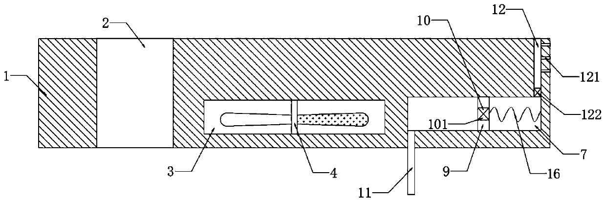
[0030] refer to Figure 3-4 , Different from Embodiment 1, the inner wall of the strip groove 7 is embedded with a helical coil 8, and the aquatic plant placement groove 2 is provided with a rubber ring 14, and the rubber ring 14 is made of a rubber material with good elasticity. And fixedly connect the limit block on the inner wall of the aquatic plant placement groove 2, can prevent that the rubber ring 14 slips and falls into the river water and short circuit occurs.

[0031] The side wall of the rubber ring 14 is fixedly connected with two conductive sheets 141, the two ends of the helical coil 8 are respectively coupled with the two conductive sheets 141, and the inner wall of the aquatic plant placement tank 2 is embedded with two conductive blocks 15, and the floating plate 1 A warning light 13 coupled with two conductive blocks 15 is installed at the upper end of the top.

[0032] It should be noted that the connection and installation methods of the conductive sheet ...


PUM


Abstract

The invention discloses a bioremediation device for treating river pollution, which comprises a floating plate, an aquatic plant placement groove is formed in the upper end of the floating plate; a circular groove is formed in the side wall of the floating plate; a water wheel is rotatably connected to the inner bottom of the circular groove; one blade of the water wheel is made of iron; a water inlet and a water outlet which are communicated with the circular groove are respectively formed in two opposite side walls of the floating plate; a strip-shaped groove is formed in the side wall of the floating plate, a sliding plug made of magnetic materials is connected into the strip-shaped groove in a sealed and sliding mode, the sliding plug is elastically connected to the inner wall of the strip-shaped groove through a spring, and an air inlet pipe and an air outlet pipe which are communicated with the strip-shaped groove are fixedly connected to the floating plate. Air on the river surface is pumped into river water through kinetic energy of the river, the oxygen content in the river water is greatly increased, life activities of various aerobic microorganisms and other organisms inthe river water are promoted, then the decomposition speed of pollutants in the river is increased, and the bioremediation period is shortened.

Description

technical field [0001] The invention relates to the technical field of equipment related to ecological and environmental protection, in particular to a bioremediation device for controlling river pollution. Background technique [0002] Due to the excessive discharge of industrial sewage and domestic sewage, the eutrophication of the river water body makes the water body black and smelly, which not only affects the landscape, but also affects people's life and health. To solve this problem, floating islands are often set up on the river surface. Plant rich-rooted aquatic plants to purify river water. [0003] However, planting plants alone to purify river water not only takes a long repair period, but also has limited root length, which cannot treat pollutants in deep water areas; in addition, conventional bioremediation devices can only treat pollutants in the river water at the microscopic level, such as COD, etc. , There is no treatment capacity for household garbage flo...

Claims


Application Information

Patent Timeline
IPC IPC(8): C02F9/14E02B15/10
CPCC02F1/008C02F3/02C02F3/32C02F2103/007C02F2203/006C02F2209/36E02B15/10
Inventor 曹钰坤陈锦波
Owner 曹钰坤
Why Eureka
Try Eureka