
GOA array substrate and preparation method thereof

An array substrate and array layer technology, applied in semiconductor/solid-state device manufacturing, semiconductor/solid-state device components, instruments, etc., can solve problems such as short circuit between signals, heating capacitance effect, black screen of display panel, etc., to increase deposition thickness, Prevents short circuits and improves stability

Active Publication Date: 2020-08-11
SHENZHEN CHINA STAR OPTOELECTRONICS SEMICON DISPLAY TECH CO LTD
View PDF4 Cites 0 Cited by
  • Summary
  • Abstract
  • Description
  • Claims
  • Application Information

AI Technical Summary

Problems solved by technology

[0003]In the existing busline design of GOA array substrate, the clock signal driven by GOA will be introduced from the bus to the GOA unit by means of jumper lines. The GOA unit is prone to taper angle (cone angle) when the first metal layer (M1) is deposited at the position where the cross-line ends, so that the thickness of the insulating layer deposited here is not uniform, and it is thinner than the horizontal position.
When there is a high-frequency signal at the clock signal (CK), it is easy to generate heat between the first metal layer (M1) and the second metal layer (M2), and the capacitive effect of the two is easy to break down the insulating layer, resulting in a short circuit between the signals , which triggers the overcurrent protection set by the display panel, resulting in a black screen of the display panel

Method used


Image

  • GOA array substrate and preparation method thereof
  • GOA array substrate and preparation method thereof

Examples


Embodiment Construction

[0024] The technical solutions in the embodiments of the present application will be clearly and completely described below in conjunction with the drawings in the embodiments of the present application. Apparently, the described embodiments are only some of the embodiments of this application, not all of them. Based on the embodiments in this application, all other embodiments obtained by those skilled in the art without making creative efforts belong to the scope of protection of this application.

[0025] In the description of the present application, it should be understood that the terms "center", "longitudinal", "transverse", "length", "width", "thickness", "upper", "lower", "front", " Orientation indicated by rear, left, right, vertical, horizontal, top, bottom, inside, outside, clockwise, counterclockwise, etc. The positional relationship is based on the orientation or positional relationship shown in the drawings, which is only for the convenience of describing the a...


PUM


Abstract

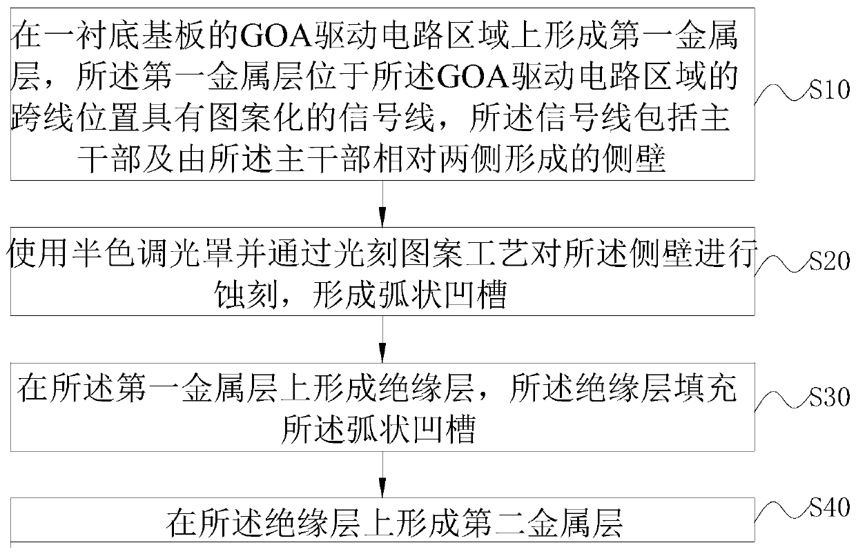
The invention discloses a GOA array substrate and a preparation method thereof. The GOA array substrate comprises a substrate body and a GOA drive circuit arranged on the substrate body. The GOA drivecircuit comprises a plurality of connected GOA units, and each GOA unit comprises a thin film transistor array layer, a first metal layer formed on the thin film transistor array layer, an insulatinglayer arranged on the first metal layer and a second metal layer arranged on the insulating layer; the first metal layer is provided with a patterned signal line at a position crossing the second metal layer, the signal line comprises a trunk part and side walls formed by two opposite sides of the trunk part, and each side wall is provided with an arc-shaped groove. According to the embodiment ofthe invention, the short circuit of the signal line formed by the first metal layer and the signal line formed by the second metal layer at the overline position can be prevented, and the stability of the GOA drive circuit in the GOA array substrate is further improved.

Description

technical field [0001] The present application relates to the field of display technology, in particular to a GOA array substrate and a preparation method. Background technique [0002] With the continuous development of LCD panel technology, Gate Driver on Array (GOA) technology is widely used in the circuit design of LCD panels. For this reason, more and more related circuit traces are also integrated. to the panel. GOA technology uses the existing thin film transistor liquid crystal display (Thin Film Transistor Liquid Crystal Display, referred to as TFT-LCD) array process to manufacture the gate row drive circuit on the array (Array) substrate to realize the driving method of progressive scanning of the gate of a technology. GOA technology can save the gate chip (Gate IC), which is beneficial to the design and cost reduction of the narrow border (narrow border) on the gate driver (Gate Driver) side of the display screen, and has been widely used and researched. [000...

Claims


Application Information

Patent Timeline
Patent Type & Authority Applications(China)
IPC IPC(8): H01L27/12H01L21/77
CPCH01L27/1288H01L27/1248H01L27/1244H01L27/124H01L21/76885H01L21/76834H01L23/5283G02F1/136236G02F1/136286G02F1/1368
Inventor 肖邦清
Owner SHENZHEN CHINA STAR OPTOELECTRONICS SEMICON DISPLAY TECH CO LTD
Learn More