High-order LCLCL direct-current converter based on harmonic optimization and parameter design method

A DC converter and parameter design technology, applied in the direction of DC power input conversion to DC power output, high-efficiency power electronic conversion, output power conversion device, etc., can solve problems such as efficiency reduction

Active Publication Date: 2020-08-11
HARBIN INST OF TECH
View PDF11 Cites 14 Cited by
  • Summary
  • Abstract
  • Description
  • Claims
  • Application Information

AI Technical Summary

Problems solved by technology

[0007] Aiming at the problem that the existing LLC resonant converter needs to perform frequency conversion control to reduce efficiency in order t...

Method used


Image

  • High-order LCLCL direct-current converter based on harmonic optimization and parameter design method
  • High-order LCLCL direct-current converter based on harmonic optimization and parameter design method
  • High-order LCLCL direct-current converter based on harmonic optimization and parameter design method

Examples


specific Embodiment approach 1

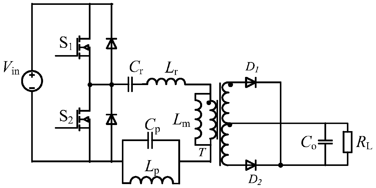
[0128] Specific implementation mode 1. Combination figure 1 As shown, the first aspect of the present invention provides a high-order LCLCL DC converter based on harmonic optimization, including a switching tube S 1 , switch tube S 2 , Resonant capacitance C r , Resonant inductance L r , transformer T, band stop filter inductor L p , Band stop filter capacitor C p , Diode D 1 , Diode D 2 and output capacitor C 0 ,

[0129] Band stop filter inductor L p and bandstop filter capacitor C p are connected in parallel to form a band-stop filter;

[0130] Switch tube S 1 The drain is connected to the power supply V in positive pole of the switch tube S 1 The source is connected to the switch S 2 The drain of the switch tube S 2 The source is connected to the power supply V in the negative pole;

[0131] Resonant capacitance C r , Resonant inductance L r , the primary side of the transformer T and the band-stop filter are connected in series in the switch tube S 2 ...

specific Embodiment approach 2

[0136] Specific embodiment two, combine Figure 2 to Figure 25 As shown, another aspect of the present invention also provides a parameter design method of a high-order LCLCL DC converter based on harmonic optimization. design, including:

[0137] Step 1: Analyze the DC converter when the secondary side of the transformer T is turned on, and obtain the resonant capacitance C r , Resonant inductance L r with the resonant frequency f of the band-stop filter r1 and the resonant frequency f of the bandstop filter r2 ;

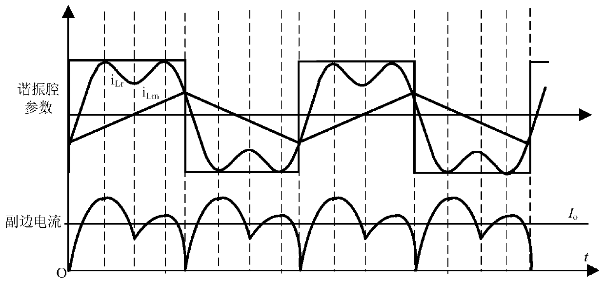
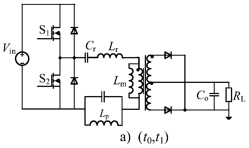
[0138] Step 2: When the power supply V in The frequency f is at f r1 and f r2 In between, the working mode of the DC converter in one switching cycle is analyzed to obtain the working status of the DC converter in different stages of a switching cycle;

[0139] Step 3: According to the working state of the DC converter, convert the DC converter to obtain an equivalent conversion circuit; perform step-down and frequency conversion control on the equivalent c...

specific Embodiment

[0255] (1) Determine the system specification (input voltage range) according to the parameter design index;

[0256] (2) According to the input voltage range and the output voltage index, the maximum and minimum voltage gains of the resonant network are determined when the transformation ratio of the transformer is reasonably selected. Among them, the minimum voltage gain is determined by the inductance coefficient.

[0257] (3) From the transformer ratio determined above, calculate the equivalent load resistance of the secondary side.

[0258] (4) A reasonable quality factor Q is obtained from the inductance coefficient in the second step and the summary law of the gain curve.

[0259] (5) Finally, substitute the selected K, quality factor Q and inductance into the resonant network formula to obtain the values ​​of each parameter.

[0260] In order to verify the feasibility of the selected topology and parameter design, a prototype with the following indicators was built: ...


PUM


Abstract

The invention discloses a high-order LCLCL direct-current converter based on harmonic optimization and a parameter design method, and belongs to the field of power supply power converters. The invention aims to solve the problem that the LLC resonant converter needs to be subjected to frequency conversion control to realize stable voltage output, and the efficiency is reduced. The converter comprises a band-stop filter inductor and a band-stop filter capacitor which are connected in parallel to form a band-stop filter. The drain electrode of the switch tube S1 is connected with the positive electrode of the power supply, the source electrode of the switch tube S1 is connected with the drain electrode of the switch tube S2, and the source electrode of the switch tube S2 is connected with the negative electrode of the power supply. The resonant capacitor, the resonant inductor, the primary side of the transformer and the band elimination filter are sequentially connected in series between the drain electrode and the source electrode of the switching tube S2. One end of the secondary side of the transformer is connected with the anode of a diode D1, the cathode of the diode D1 is connected with the cathode of a diode D2, and the anode of the diode D2 is connected with the other end of the secondary side of the transformer. An output capacitor is connected between the center tap ofthe secondary side of the transformer and the cathode of the diode D2. The converter has a wide variable-frequency voltage regulation curve and a high-slope drop gain curve.

Description

technical field [0001] The invention relates to a high-order LCLCL DC converter based on harmonic optimization and a parameter design method, and belongs to the technical field of power converters. Background technique [0002] In the field of DC / DC power converters, the power density and efficiency of the power supply are two important indicators to evaluate its performance. Increasing the switching frequency of the converter can improve the efficiency of the switching power supply, but the switching loss is greatly increased due to the increase of the switching frequency. As the frequency increases, its efficiency will also decrease significantly with the increase of frequency. Therefore, high-frequency DC / DC power converters mostly use LC resonance to realize the working state of soft switching, thereby eliminating switching losses and improving the efficiency of power converters. work efficiency. At present, LLC high-frequency resonant converters are widely used, such a...

Claims


Application Information

Patent Timeline
IPC IPC(8): H02M3/335H02M1/32
CPCH02M3/33523H02M3/33569H02M1/32H02M1/0058Y02B70/10
Inventor 张相军戴明聪管乐诗王懿杰徐殿国井嘉晨
Owner HARBIN INST OF TECH
Why Eureka
Try Eureka