
Efficient circulating self-crystallization solid-liquid separation device

A solid-liquid separation and self-crystallization technology, which is applied in the direction of separation method, sedimentation separation, sediment separation by centrifugal force, etc., can solve the problems of low efficiency of solid-liquid separation of fine sand, pollution of the environment, etc.

Pending Publication Date: 2020-08-14
国能朗新明环保科技有限公司
View PDF7 Cites 3 Cited by
  • Summary
  • Abstract
  • Description
  • Claims
  • Application Information

AI Technical Summary

Problems solved by technology

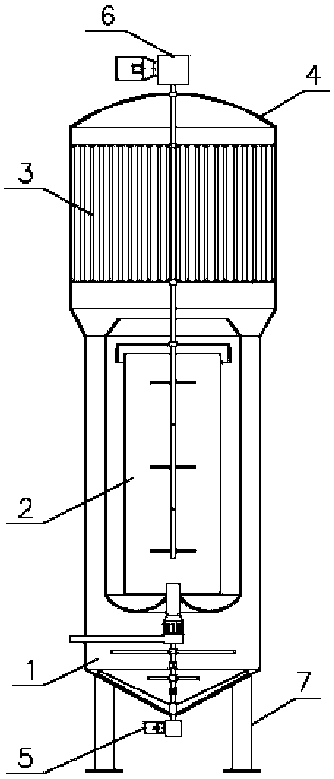
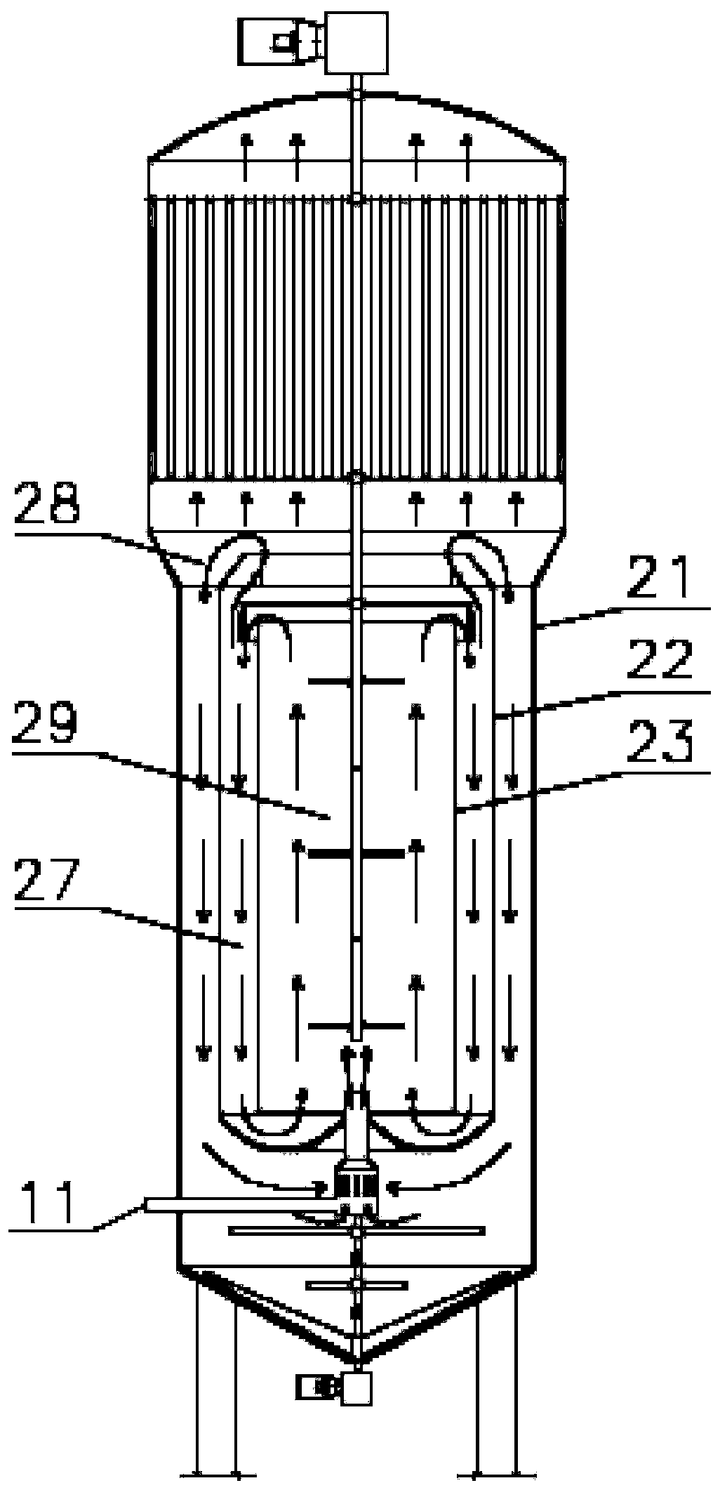
[0005] The present invention aims to solve the problem of low efficiency of solid-liquid separation and environmental pollution of micro-sand in the prior art, and provides a self-crystallization device with high-efficiency solid-liquid separation. Through special structural design, no need to add micro-sand or powder ash. The sludge is sucked back into the circulation crystallization zone. After the fine particles in the sludge zone enter the circulation crystallization zone, under the double action of stirring and mixing by the agitator in the flocculation zone and the internal circulation flow, crystallization nuclei are provided for the generation of sludge particles. , using the principle of induced crystallization heterogeneous nucleation to form crystalline particles, and the sludge that flows back into the flocculation zone accelerates the flocculation reaction process of the influent, realizing self-crystallization inside the device and achieving the effect of solid-liquid separation

Method used


Image

  • Efficient circulating self-crystallization solid-liquid separation device
  • Efficient circulating self-crystallization solid-liquid separation device
  • Efficient circulating self-crystallization solid-liquid separation device

Examples


Embodiment 1

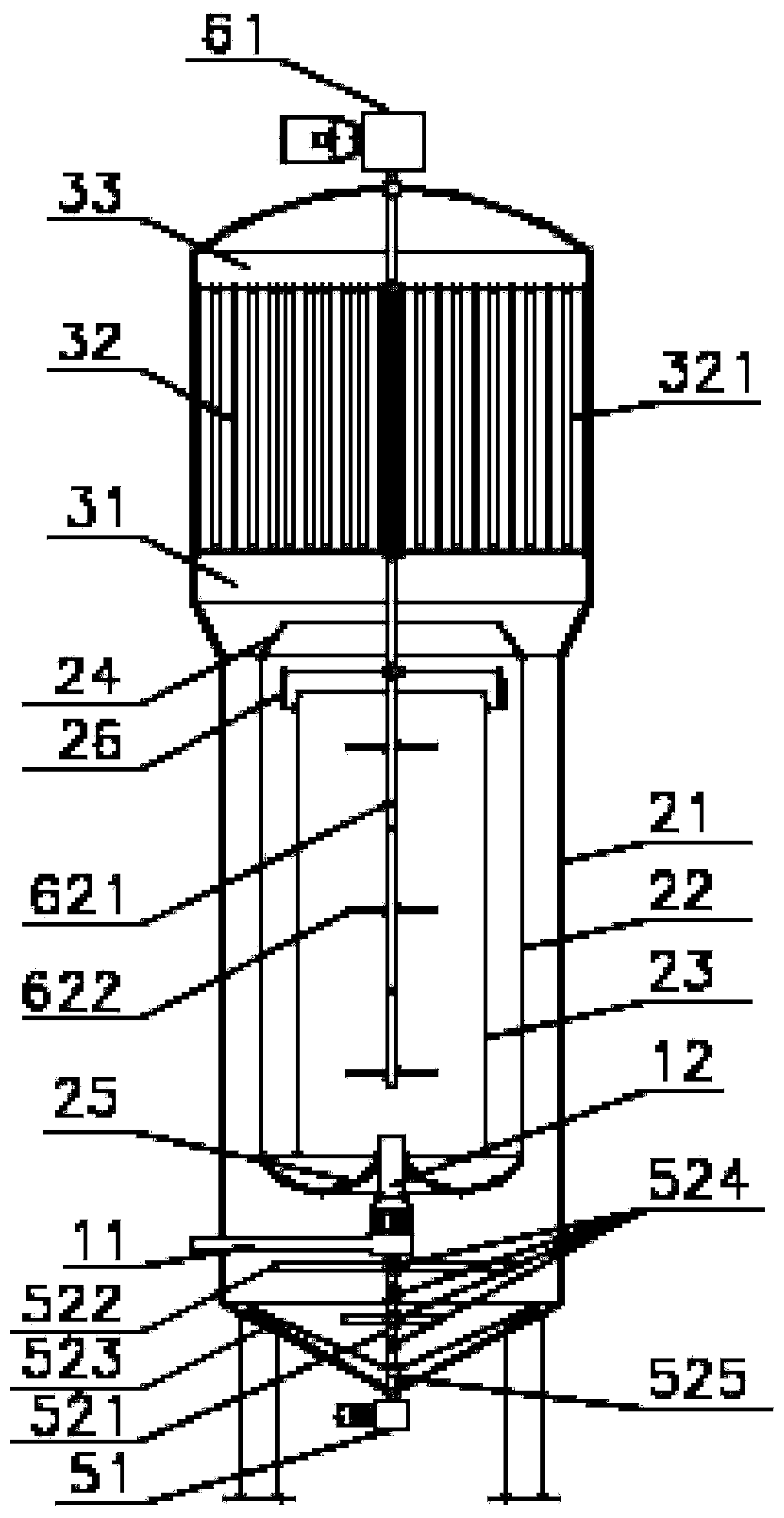
[0054] Such as Figure 1-16 As shown, a high-efficiency circulating self-crystallization solid-liquid separation device includes a sludge area 1, a circulating crystallization area 2, a solid-liquid separation area 3, and a head 4 arranged sequentially from bottom to top, and the sludge area 1 is connected. The first power facility 5, the second power facility 6 connected to the solid-liquid separation zone 3 and the legs 7 arranged outside the bottom of the sludge zone 1, the sludge zone 1, the circulating crystallization zone 2, and the solid-liquid separation zone 3 and the head 4 form a closed structure;

[0055] The sludge area 1 includes a water inlet pipe 11, a negative pressure component 12 connected to the inner end of the water inlet pipe 11, and a sludge discharge pipe 13 located on one side of the sludge area 1. The bottom of the sludge area 1 is tapered; the negative pressure component 12 includes Outer cover 121, body 122 and gradual expansion part 123; Outer co...


PUM


Abstract

The invention provides an efficient circulating self-crystallization solid-liquid separation device. The device comprises a sludge area (1), a circulating crystallization area (2) and a solid-liquid separation area (3); the circulating crystallization area (2) comprises an outer cylinder (21), a middle cylinder (22) and an inner cylinder (23); the circulating crystallization area (2) and a negative pressure part (12) of the sludge area (1) form an inner circulation channel (27) and an outer circulation channel (28), a first power facility (5) is connected with a first stirring part (52) capable of rotating clockwise and anticlockwise, and the solid-liquid separation area (3) comprises a plurality of separation pipes (321). According to the device, sludge fine particles entering the circulating crystallization area (2) are sucked back and refluxed; crystallization crystal nucleuses are provided for generation of sludge crystallization particles, the principle of induced crystallizationheterogeneous nucleation is utilized, the crystallization particles are formed, sludge flowing back into a flocculation zone (29) accelerates the flocculation reaction process of inlet water, self-crystallization in the device is achieved, and finally the effect of solid-liquid separation is achieved through a suspended sludge layer.

Description

technical field [0001] The invention relates to the technical field of water treatment, in particular to a high-efficiency circulation self-crystallization solid-liquid separation device. Background technique [0002] The solid-liquid separation equipment in the prior art needs to add micro-sand or powder ash as crystal seeds, and meanwhile the utilization rate of the crystal seeds is low. And solid-liquid separation equipment when dealing with low-temperature and low-turbidity water, the growth of particles in the flocculation reaction zone is slow, and the stability of agglomerated flocs is poor. The problem. [0003] In the prior art, micro-sand or powdered carbon is often added to provide high-density coagulation nuclei for the agglomerates in the flocculation zone, thereby increasing the density of the agglomerates in the flocculation zone. Due to the problem of consumption of micro-sand or powder ash, there is a need to replenish it regularly, and this technology has...

Claims


Application Information

Patent Timeline
IPC IPC(8): C02F1/52B01F7/18B01F5/10B01D21/06B01D21/24B01D21/26B01D21/28
CPCC02F1/5281B01D21/265B01D21/267B01D21/28B01D21/245B01D21/06C02F2001/5218B01F25/52B01F27/90
Inventor 马跃华王云盛飞陈峰
Owner 国能朗新明环保科技有限公司
Learn More