Novel hemostatic clip

A technology of hemostatic clips and clips, applied in the field of hemostatic clips, which can solve the problems of tissue tearing, expansion of release aperture, clip falling off, etc., and achieve the effect of avoiding tissue tearing

Pending Publication Date: 2020-08-18
MICRO TECH (NANJING) CO LTD
View PDF0 Cites 10 Cited by
  • Summary
  • Abstract
  • Description
  • Claims
  • Application Information

AI Technical Summary

Problems solved by technology

[0004] like figure 1 In the prior art shown in , the proximal end of the clip realizes the locking of the clip assembly by setting the shrapnel A, and due to the unavoidable organization trapped between the two clips during the use of the hemostatic clip, the hemostatic clip used for locking The inaccurate positioning of the body and the expansion of the release aperture lead to the early release of the control line, and finally lead to technical problems such as undesired early falling off of the clip before the locked state, tearing of the tissue, etc.

Method used


Image

  • Novel hemostatic clip
  • Novel hemostatic clip
  • Novel hemostatic clip

Examples


Embodiment 1

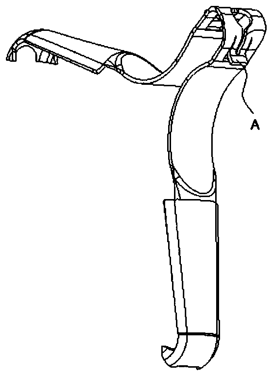
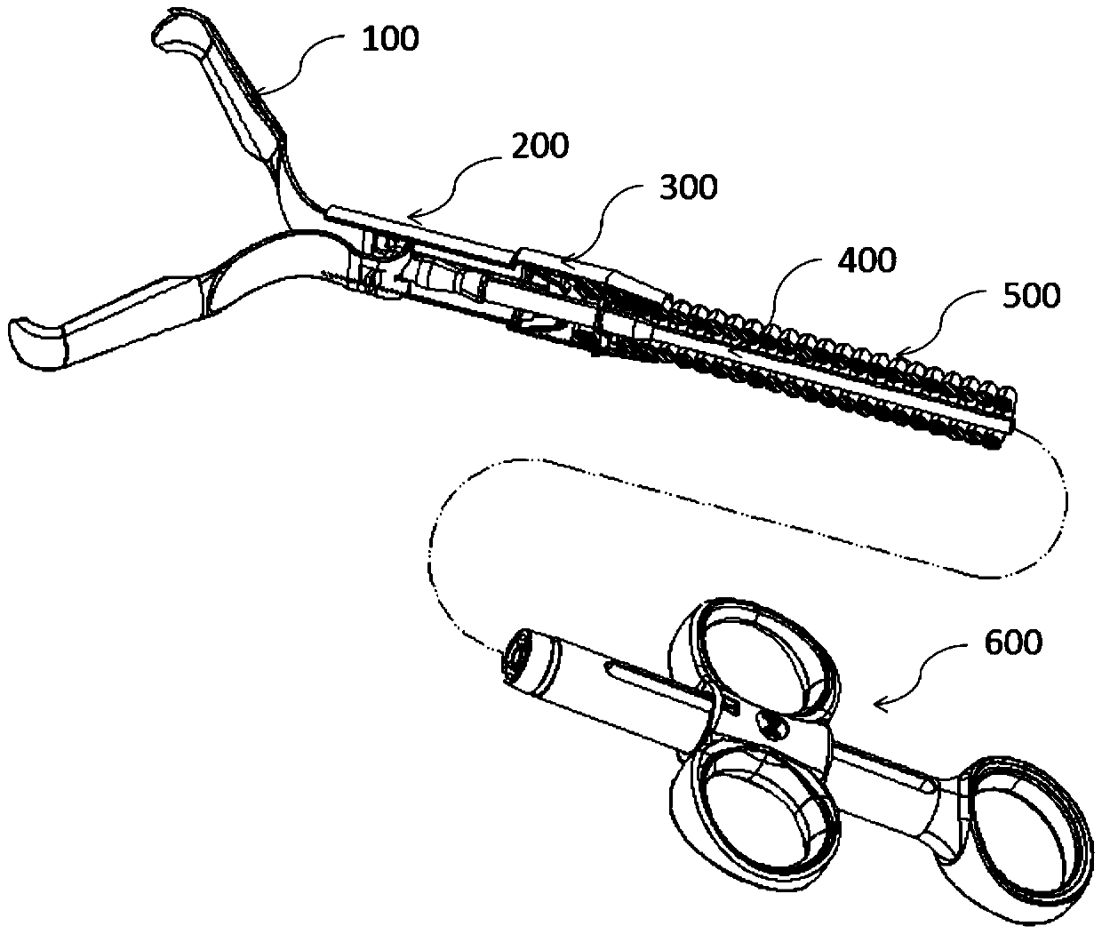
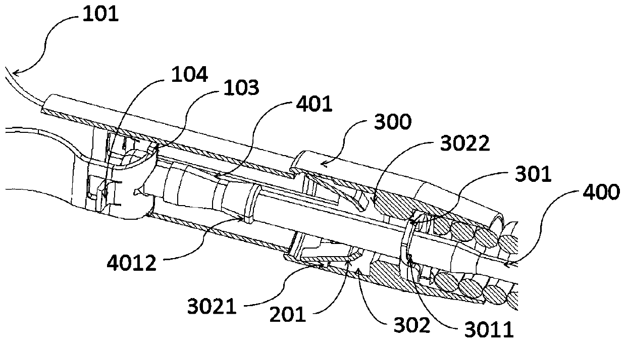
[0060] Such as Figure 1-5 As shown, in this embodiment, the hemostatic clip has a handle 600 on the proximal side, a clip assembly on the distal side, a sheath 500 between the handle 600 and the clip assembly 100, and a control wire 400 in the sheath 500, The distal end of the sheath tube 500 has a fixing seat 300 , and the distal end of the control wire 400 has a release portion 401 . Wherein, the clip assembly includes: a clip body 100, which has two clip arms 101, and a transition connection portion 102 connecting the two clip arms 101 proximally; channel, and the proximal side of the clip base is releasably connected with the fixing base. The proximal side of the clamp seat 200 has a retainer 201, and the fixed seat 300 has an open release chamber 302 towards the distal side. The distal tail of the retainer 201 is in a natural state and the locking groove 3021 on the distal side wall of the release chamber 302 Releasable snap connection, when the clip body 100 is in the...

Embodiment 2

[0077] Such as Figure 11a , Figure 11b As shown, the structure of the safety mechanism 301 in Embodiment 1 is transformed. In this Embodiment 2, the outer periphery of the distal end surface of the safety mechanism 301 forms an equilateral triangle. Do arc chamfering. There is a through hole 3013 in the center of the safety mechanism, and each radially protruding protrusion 3011 on the inner wall of the through hole 3013 has a bend that deflects toward the proximal end. When sliding to the distal side, it can pass through the safety mechanism 301 more smoothly, and when the part of the diameter reducing part 4012 with the largest radial length exceeds the proximal surface of the protruding part 3011, it can provide a higher abutment force and prevent it to the greatest extent. The line of control is again moved distally to achieve a better insurance effect. In this embodiment, the proximal surface of the safety mechanism 301 has the sheath tube abutting portion 3012 arran...

Embodiment 3

[0079] Such as Figure 12 As shown, the structure of the insurance mechanism 301 in Embodiment 1 is transformed. In Embodiment 3, the distal end surface of the safety mechanism has a circular structure, and six protrusions 3011 protruding radially inward are arranged at equal intervals on the inner peripheral wall of the safety mechanism 301, the protrusions extend radially, and the six protrusions It provides a more reliable limit capability and better ensures the one-way movement of the control line. At the same time, the proximal end surface of the safety mechanism 301 has a circular end surface adapted to the distal surface of the sheath, so that the proximal surface and the distal surface of the safety mechanism 301 are fully in contact with the sheath tube and the fixing seat respectively, and the lifting device is stable and reliable The connectivity performance, thus ensuring the effectiveness of the insurance agency.

[0080] Of course, as the deformation method of ...


PUM


Abstract

A hemostatic clip has a handle on a proximal side, a clip assembly on a distal side, and a sheath tube located between the handle and the clip assembly and a control wire located in the sheath tube; the distal end of the sheath tube has a fixed seat and the distal end of the control wire has a release part; the clip assembly includes a clip body and a clip seat; a transition connecting part of theclip body is provided with a release hole; the release part located on the distal side of the control wire is connected with the release hole in a releasable mode; and the transition connecting partis provided with a radial limiting part so as to limit expansion of the release hole in the radial direction. On the basis that the complexity of the overall structure of the clip is not increased, the technical problem that the control wire is released in advance is solved, it is ensured that the clip assembly cannot be disengaged from the control wire too early before locking, and the technicalproblems of tissue tearing, inaccurate clip positioning and the like are avoided.

Description

technical field [0001] The invention relates to a hemostatic clip used in tissue closure for minimally invasive surgery, belonging to the field of medical devices. Background technique [0002] Existing hemostatic clips are sent through the endoscopic clamp channel to perform hemostasis or clamping operations on the wound surface. The purpose of hemostasis and clipping is mainly achieved by mechanically compressing the blood vessels and surrounding tissues with the clamps. The principle of hemostasis is similar to surgical suture or ligation of blood vessels. , which is a mechanical method, does not cause coagulation, denaturation, or necrosis of mucosal tissue. After the metal hemostatic clip treatment, the local tissue inflammation process forms granulomas, which fall off by themselves and are excreted through the digestive tract. The operation has the advantages of less damage, faster hemostasis, lower incidence of rebleeding, fewer complications, and definite curative e...

Claims


Application Information

Patent Timeline
Patent Type & Authority Applications(China)
IPC IPC(8): A61B17/122A61B17/128
CPCA61B17/1227A61B17/1285
Inventor 金鸿雁李常青沈正华宋冉马小军
Owner MICRO TECH (NANJING) CO LTD
Why Eureka
Try Eureka