Steel tube welding system and technology

A welding system and steel pipe technology, applied in welding equipment, welding equipment, auxiliary welding equipment, etc., can solve the problems of observing the best initial position of the steel plate, insufficient contact between the steel plate and the pipe, and the influence of the initial height grinding work, etc. The effect of handling pipes, safe and convenient use, and reducing labor intensity

Inactive Publication Date: 2020-08-18
林进卓
View PDF7 Cites 6 Cited by
  • Summary
  • Abstract
  • Description
  • Claims
  • Application Information

AI Technical Summary

Problems solved by technology

In the process of using the welding device, the inventor found that when using the steel wire plate to grind the welding place, the initial height of the steel wire plate has a great influence on the grinding effect, because the initial height is too high, the pipe is easy to touch the installation block and makes the installation The block is worn, the initial height is too low, the contact between the steel wire plate and the pipe is insufficient, and the grinding effect is affected. Although there is a buffer spring, the initial height still has an important impact on the grinding work. The original structure does not It is convenient for the staff to visually observe whether the steel wire plate has reached the best initial position

Method used


Image

  • Steel tube welding system and technology
  • Steel tube welding system and technology
  • Steel tube welding system and technology

Examples


Embodiment

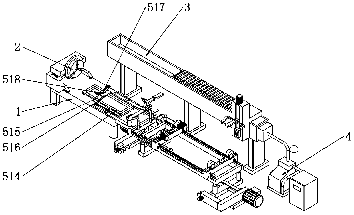
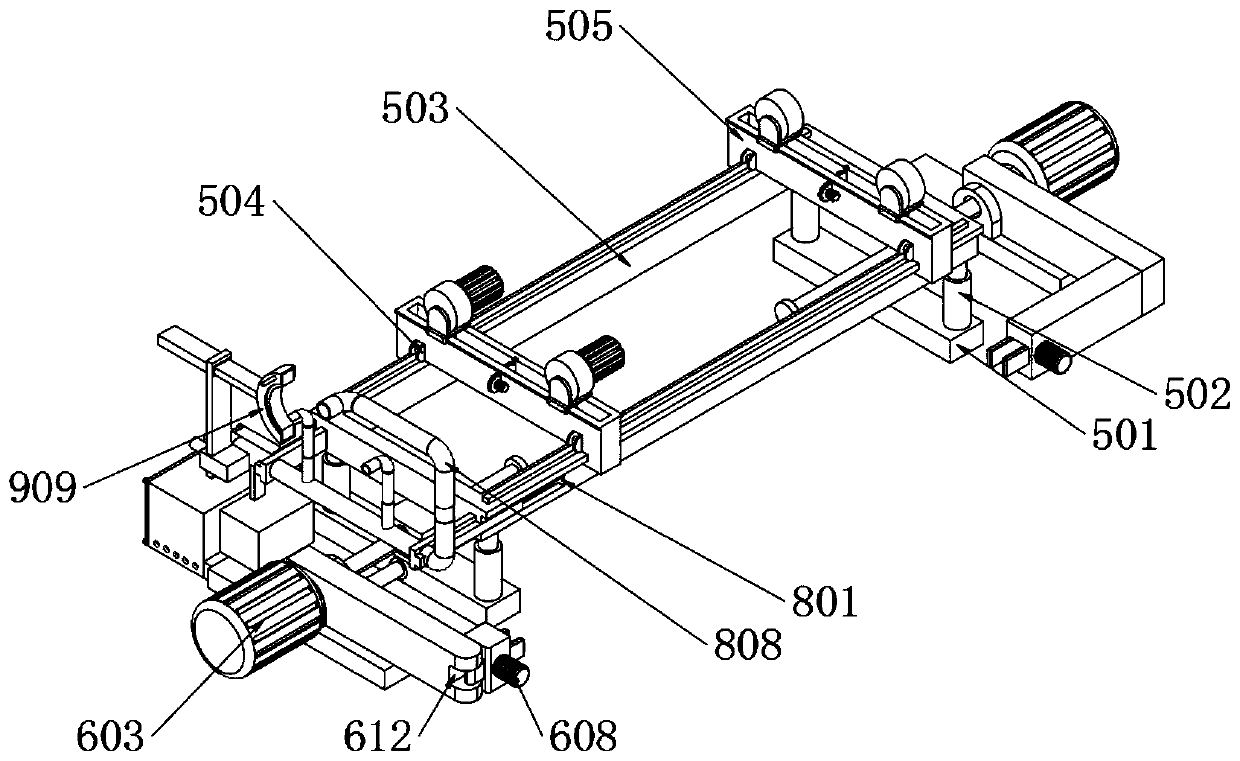
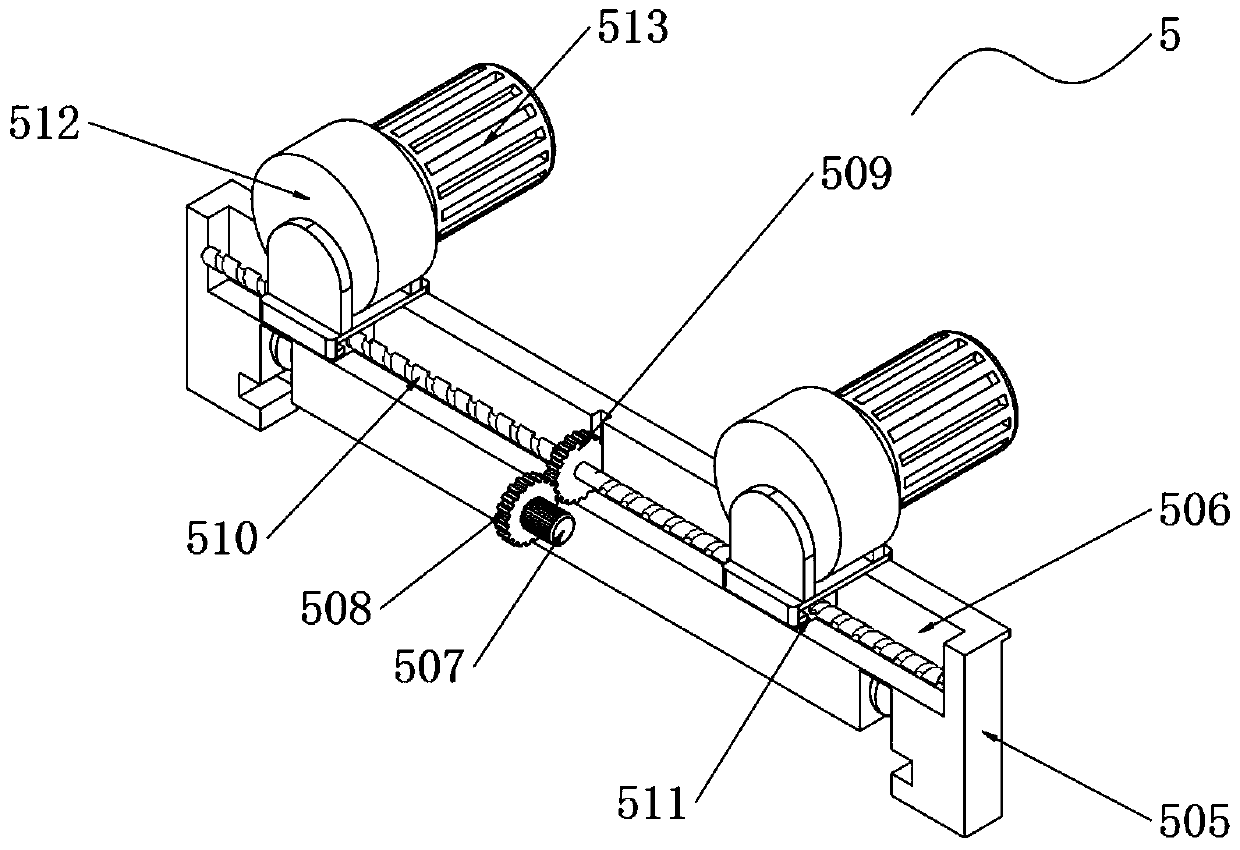
[0037] Example: such as Figure 1-13As shown, a steel pipe welding system includes a welding support frame 1, a support adjustment assembly 5, a feeding fastening assembly 6, a grinding preheating assembly 7, a chip removal and degassing assembly 8, and a heat preservation and cooling assembly 9. The grinding preheating assembly The side wall of the preheating installation groove 708 of the component 7 is fixedly connected with a detection motor 715, and the output shaft of the detection motor 715 is fixedly connected with the rotating column 716 located in the preheating installation groove 708, and the upper end of the rotating column 716 with a sliding space 717 is open and closed. Built-in pressure column 718, the bottom end of pressure column 718 is fixedly connected with the bottom wall of sliding space 717 through return spring 719, the bottom wall of sliding space 717 is fixedly connected with contact pressure sensor 720, the two sides of pressure column 718 are fixedly...


PUM


Abstract

The invention discloses a steel tube welding system and technology. The side wall of a preheating installation groove of a grinding and preheating assembly is fixedly connected with a detection motor.An output shaft of the detection motor is fixedly connected with a rotating column located in the preheating installation groove. The upper end of the rotating column provided with a sliding space isprovided with an opening, and a pressing column is arranged in the rotating column. The bottom end of the pressing column is fixedly connected with the bottom wall of the sliding space through a reset spring. The bottom wall of the sliding space is fixedly connected with a contact type pressure sensor. The two sides of the pressing column are fixedly connected with positioning columns. The positioning columns slide in sliding grooves formed on the pressing column. The bottom end of a steel wire plate is fixedly connected with a convex block. The side wall of the preheating installation grooveis fixedly connected with a single-chip microcomputer controller and an indicator light. The single-chip microcomputer controller receives the signal of the contact pressure sensor, and controls thedetection motor and indicator light to act.

Description

technical field [0001] The invention relates to the technical field of pipeline welding, in particular to a steel pipe welding system and a welding process. Background technique [0002] In the past 20 years, with the development of digitization, automation, computer and mechanical design technology, and the high emphasis on welding quality, automatic welding has developed into an advanced manufacturing technology, and automatic welding equipment has played an important role in the application of various industries The role is getting bigger and bigger, and the scope of application is expanding rapidly. In modern industrial production, the mechanization and automation of the welding production process is an inevitable trend in the modernization of the welding mechanism manufacturing industry. [0003] When automatically welding pipes outdoors, when fixing pipes with different diameters, the staff needs to manually adjust the distance between the support wheels according to t...

Claims


Application Information

Patent Timeline
Patent Type & Authority Applications(China)
IPC IPC(8): B23K31/02B23K37/00B23K37/053B24B27/033B24B41/04B24B41/06B24B47/12B24B47/22
CPCB23K31/02B23K37/00B23K37/003B23K37/053B24B27/033B24B41/04B24B41/067B24B47/12B24B47/22
Inventor 林进卓
Owner 林进卓
Why Eureka
Try Eureka