Electron bombardment ionization source device, ionization bombardment method and substance analysis method

A technology of electron bombardment ionization and source device, applied in the field of electronics, can solve the problems of application limitation, low ionization efficiency, no, etc., and achieve the effect of accurate qualitative analysis

Active Publication Date: 2020-08-18
NAT INST OF METROLOGY CHINA
View PDF6 Cites 1 Cited by
  • Summary
  • Abstract
  • Description
  • Claims
  • Application Information

AI Technical Summary

Problems solved by technology

[0007] However, for chromatography-mass spectrometry schemes, chromatographic separation takes time. Even if fast chromatography is used, the separation time is quantified in minutes. This is obviously not the best solution for applications that pursue analysis speed. best solution
Ultraviolet photoionization ion source technology has low ionization energy, so it hardly produces fragments, which has certain advantages for rapid analysis. However, compared with EI source, its ionization efficiency is lower, and its ionization energy is constant, so it cannot be used for analysis. Molecules with high ionization energy are ionized
Therefore, its application is also subject to certain restrictions

Method used


Image

  • Electron bombardment ionization source device, ionization bombardment method and substance analysis method
  • Electron bombardment ionization source device, ionization bombardment method and substance analysis method
  • Electron bombardment ionization source device, ionization bombardment method and substance analysis method

Examples


Embodiment Construction

[0054] In order to more clearly illustrate the technical solutions in the embodiments of the present invention or the prior art, the following will briefly introduce the drawings that need to be used in the description of the embodiments or the prior art. Obviously, the accompanying drawings in the following description These are some embodiments of the present invention. Those skilled in the art can also obtain other drawings based on these drawings without creative work.

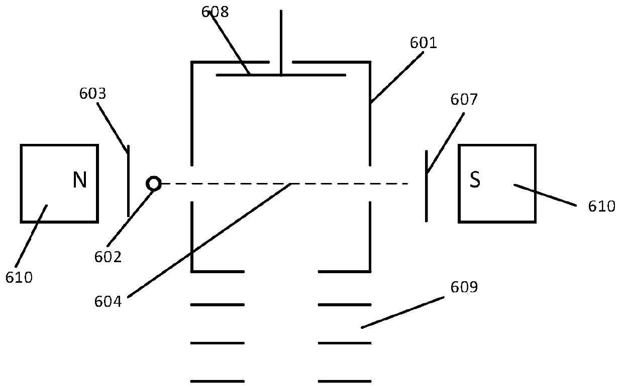
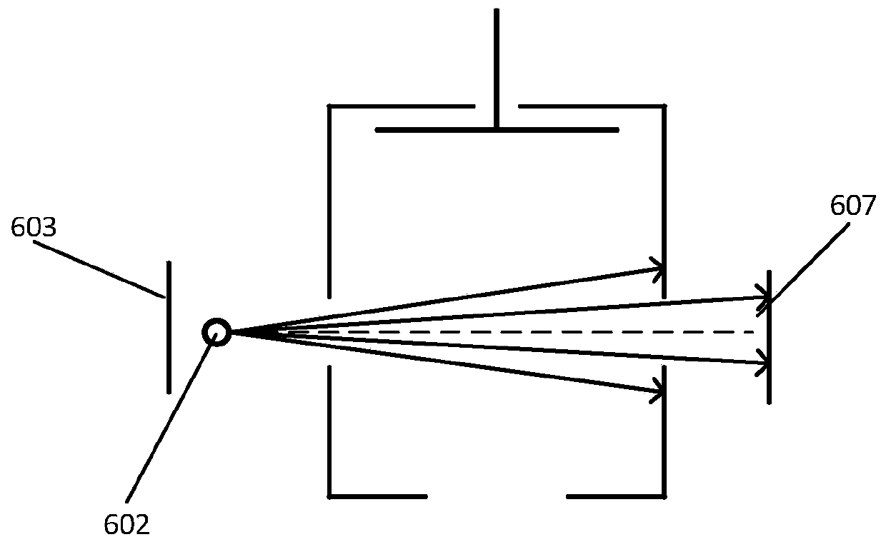
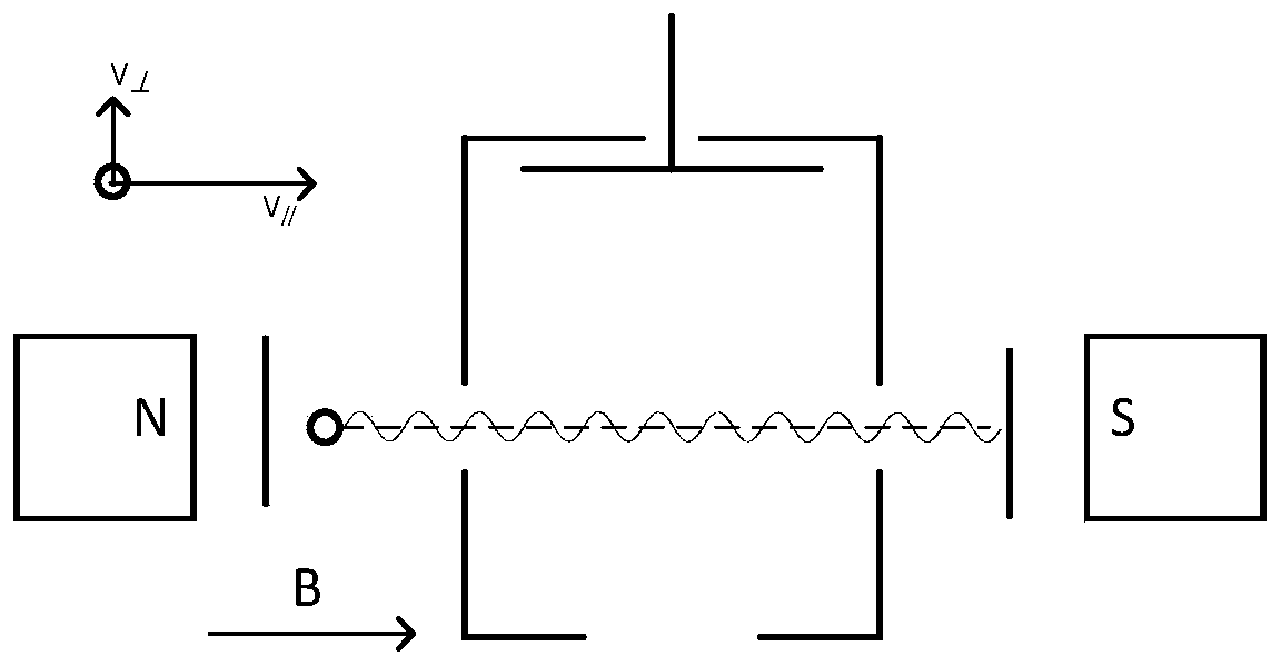
[0055] Aiming at the shortcomings of the low ionization efficiency of the electron bombardment ionization source device in the prior art, the embodiment of the present invention provides an electron bombardment ionization source device that can improve the ionization efficiency, mainly by increasing the length of the movement path of the electrons. The cross-sectional area of ​​the collision with the analyte molecules, thereby improving the ionization efficiency, and then improving the sensitivity of the el...


PUM


Abstract

The embodiment of the invention provides an electron bombardment ionization source device, an ionization bombardment method and a substance analysis method, and the device comprises the steps: placinga pair of radial acceleration electrodes at the inner side, close to an ionization chamber, of a first electron repulsion electrode and at the upper and lower parts or the front and rear parts of a first filament, and forming an electric field perpendicular to a magnetic field direction between the radial acceleration electrodes; enabling electrons overflowing from the electrified and heated first lamp filament to move in a spiral line under the acting force in the magnetic field direction, wherein the radius of the spiral line where the electrons move is increased under the action of an electric field perpendicular to the magnetic field direction, and then the actual movement path of the electrons is increased. According to the device, the electric field perpendicular to the electron motion reference axis is added, under the action of the electric field, the radius of spiral line operation of electrons is increased, then the actual operation path of the electrons in the ionization chamber is increased, the collision sectional area of the electrons and measured object molecules is increased, and then the ionization efficiency of the ion source is improved.

Description

technical field [0001] The invention belongs to the field of electronic technology, and in particular relates to an electron bombardment ionization source device, an ionization bombardment method and a material analysis method. Background technique [0002] Electron impact ionization (EI) is a traditional ion source method for mass spectrometers. It utilizes thermionic emission and is accelerated by an electric field of a certain intensity so that it has a certain energy, and then collides with the molecules of the analyte, and through energy exchange, the molecules are ionized into molecular ions, and some molecular ions will be obtained because More energy, and will be further fragmented into fragment ions. These molecular ions and fragment ions are used as the fingerprints of molecules, which can be used as the basis for judging molecular structures, and have become a standard method. The fingerprints of these molecules have been established as a standard EI source stan...

Claims


Application Information

Patent Timeline
Patent Type & Authority Applications(China)
IPC IPC(8): G01N27/64H01J49/10H01J49/14
CPCG01N27/64H01J49/10H01J49/14
Inventor 黄泽建江游方向戴新华
Owner NAT INST OF METROLOGY CHINA
Why Eureka
Try Eureka