A kind of bipolar plate, fuel cell unit, fuel cell and manufacturing method thereof

A fuel cell unit and bipolar plate technology, which is applied to fuel cells, fuel cell parts, electrical components, etc., can solve the problem of single design of interdigitated bipolar plates, ignoring the uniformity and discontinuity of the flow field in the distribution area, etc. problem, achieve the effect of strengthening fuel diffusion ability, facilitating gas transmission, and large adjustable space

Active Publication Date: 2021-07-09
浙江锋源氢能科技有限公司 +1
View PDF0 Cites 0 Cited by
  • Summary
  • Abstract
  • Description
  • Claims
  • Application Information

AI Technical Summary

Problems solved by technology

However, the current anode bipolar plates are mainly designed with parallel flow channels or parallel serpentine flow channels. The flow structure of this design leads to convection as the main transmission mode, and the diffusion and transmission ability of fuel to the catalytic layer is weak. The fuel in the catalytic layer low concentration
Due to the discontinuous characteristics of the flow channel, the interdigitated flow channel has better diffusion and transmission capacity than the parallel and serpentine flow channels; It is conducive to the discharge of the water generated by the cathode, which may easily cause the cathode to be flooded, affect the gas transmission of the cathode, and then affect the power generation performance of the battery; moreover, the design of the existing interdigitated bipolar plate is single, ignoring the influence of the distribution area on the uniformity of the flow field In addition, the cooling liquid side of the traditional interdigitated bipolar plate mostly adopts welding and sealing technology, which limits the development of fuel cell unit integration

Method used


Image

  • A kind of bipolar plate, fuel cell unit, fuel cell and manufacturing method thereof
  • A kind of bipolar plate, fuel cell unit, fuel cell and manufacturing method thereof
  • A kind of bipolar plate, fuel cell unit, fuel cell and manufacturing method thereof

Examples


Embodiment 1

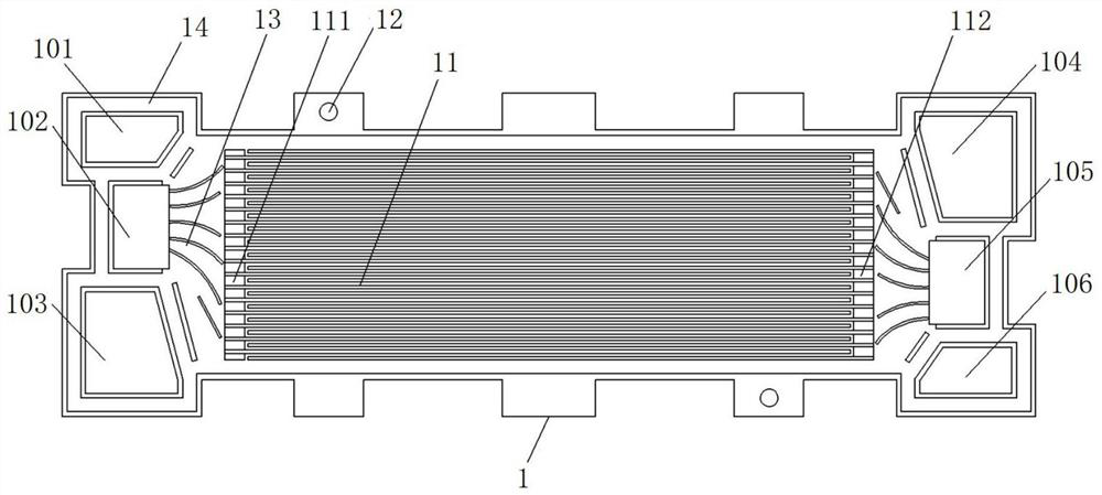
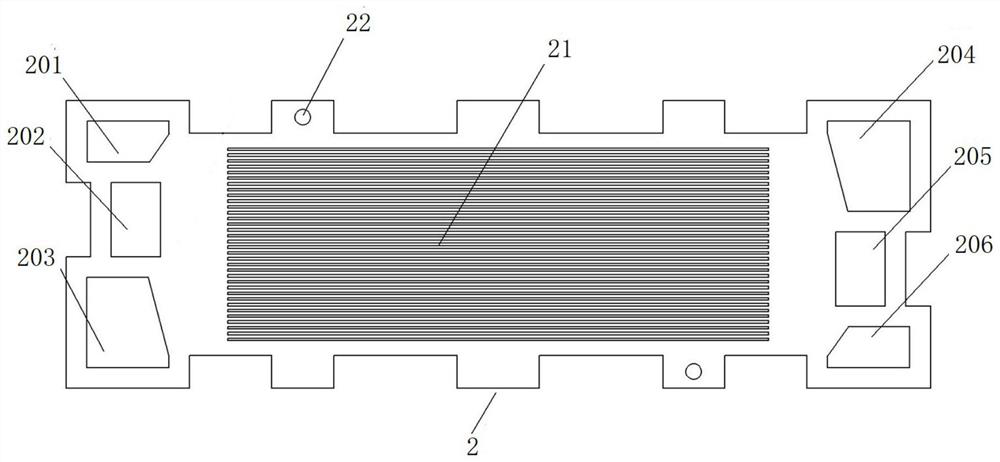
[0060] This embodiment provides a kind of bipolar plate, is used on fuel cell, as Figure 1 to Figure 7 As shown, the bipolar plate in this embodiment includes an anode plate and a cathode plate. Wherein, in this embodiment, the flow channel at the power generation area of ​​the anode plate is set as an interdigitated flow channel 11 , and the flow channel at the power generation area of ​​the cathode plate is set as a parallel flow channel 21 .

[0061] The bipolar plate provided in this embodiment can strengthen the fuel diffusion ability on the anode gas side of the fuel cell and increase the fuel concentration in the catalytic layer of the membrane electrode by setting the flow channel at the power generation area of ​​the anode plate as an interdigitated flow channel 11 , so as to improve the power generation performance of the fuel cell; at the same time, the flow channel at the power generation area of ​​the cathode plate is set as a parallel flow channel 21, so that th...

Embodiment 2

[0064] This embodiment provides a bipolar plate, compared with the previous embodiment, such as Figure 1 to Figure 7 As shown, the present embodiment is further designed as follows:

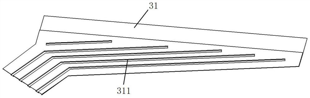
[0065] On the one hand, the design of the anode plate in this embodiment is as follows: the anode plate includes an anode plate body 1 and a fuel distribution cover plate. Wherein, the interdigitated channel 11 is located on the anode plate body 1 , and the anode plate body 1 is provided with a fuel inlet 101 , a fuel outlet 106 , an oxidant inlet 103 , and an oxidant outlet 104 . And the fuel inlet 101 and the oxidant inlet 103 on the anode plate body 1 are located at one end of the anode plate body 1 , and the fuel outlet 106 and the oxidant outlet 104 are located at the other end of the anode plate body 1 . The interdigitated channel 11 is located in the middle of the anode plate body 1 . Here, the fuel distribution cover plate includes a first fuel distribution cover plate 31 and a second ...

Embodiment 3

[0078] This embodiment provides a bipolar plate, compared with the above embodiment, such as Figure 1 to Figure 7 As shown, the present embodiment is further designed as follows:

[0079] On the one hand, a cooling liquid inlet 102 and a first cooling liquid distribution area 13 are provided on the anode plate; wherein, the first cooling liquid distribution area 13 is located between the cooling liquid inlet 102 and the interdigitated channel 11 for The coolant flowing in through the coolant inlet 102 is distributed into the coolant flow field. (Such as Figure 7 The coolant flow field 73 formed between the anode and cathode plates is shown). Preferably, when the anode plate includes the anode plate body 1 and the fuel distribution cover plate, the coolant inlet 102 and the first coolant distribution area 13 are both arranged on the anode plate body 1 . Here, the cooling liquid inlet 102 is located at one end of the anode plate body 1 provided with the fuel inlet 101 and t...


PUM


Abstract

The invention relates to a bipolar plate, a fuel cell unit, a fuel cell and a manufacturing method thereof, and relates to the technical field of fuel cells. The main technical scheme adopted is: a bipolar plate includes an anode plate and a cathode plate; wherein, the flow channels at the power generation area of ​​the anode plate are set as interdigitated flow channels; the flow channels at the power generation area of ​​the cathode plate are set to be parallel runner. The anode plate includes an anode plate body and a fuel distribution cover, and the cathode plate includes a cathode plate body and an oxidant distribution cover. A fuel cell unit includes a membrane electrode and a bipolar plate as described above. A fuel cell includes a plurality of the above-described fuel cell units. The present invention is mainly used for improving the fuel diffusion ability of the fuel cell to the catalytic layer, avoiding the flooding phenomenon of the cathode of the fuel cell, and realizing the uniform circulation of the cooling liquid side and the gas side fluid while enhancing the mass transfer.

Description

technical field [0001] The invention relates to the technical field of fuel cells, in particular to a bipolar plate, a fuel cell unit, a fuel cell and a manufacturing method thereof. Background technique [0002] The proton exchange membrane fuel cell is a new type of energy conversion device, which is used to convert the chemical energy in the fuel into electrical energy output. Proton exchange membrane fuel cells have the advantages of high energy conversion efficiency, not limited by the Carnot cycle, high operational reliability, low operating temperature, fast start-up, simple structure, and no noise. They can be widely used in the transportation industry, mobile facility power supply, Distributed power generation and other fields. The proton exchange membrane fuel cell unit is composed of bipolar plates, membrane electrodes and seals, etc., and multiple battery units can be assembled in series to form a stack structure. [0003] The power generation performance and r...

Claims


Application Information

Patent Timeline
Patent Type & Authority Patents(China)
IPC IPC(8): H01M8/0258H01M8/0265H01M8/0286H01M8/0276
CPCH01M8/0258H01M8/0265H01M8/0276H01M8/0286Y02E60/50Y02P70/50
Inventor 陈明袁蕴超沈润王海峰王利生
Owner 浙江锋源氢能科技有限公司
Why Eureka
Try Eureka