Demodulation method and circuit of signal isolation system

A technology for signal isolation and demodulation circuits, applied in the direction of logic circuits, pulse demodulation, logic circuit coupling/interface using field effect transistors, etc., can solve the problems of large overall power consumption, large bandwidth, and high comparator speed, and achieve Realize the effect of simple structure, fast transmission rate and low power consumption design

Pending Publication Date: 2020-08-18
MORNSUN GUANGZHOU SCI & TECH
View PDF4 Cites 2 Cited by
  • Summary
  • Abstract
  • Description
  • Claims
  • Application Information

AI Technical Summary

Problems solved by technology

Since the carrier signal is generally large (up to hundreds of megahertz or even gigahertz), the speed of the required comparator is high (large bandwidth), which will make the overall power consumption large
As a result, it is difficult to achieve low power design

Method used


Image

  • Demodulation method and circuit of signal isolation system
  • Demodulation method and circuit of signal isolation system
  • Demodulation method and circuit of signal isolation system

Examples


Embodiment Construction

[0034] In order to make the object, technical solution and advantages of the present invention more clear, the present invention will be further described in detail below in conjunction with the accompanying drawings and embodiments. It should be understood that the specific embodiments described here are only used to explain the present invention, not to limit the present invention.

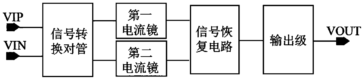
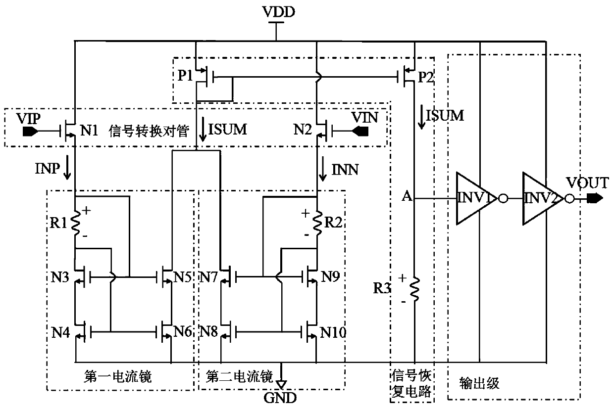
[0035] figure 2 Shown is the functional block diagram of this embodiment, including a signal conversion pair tube, a first current mirror, a second current mirror, a signal recovery circuit and an output stage electrically connected in sequence, and the signal conversion pair tube inputs a forward switch keying voltage signal VIP and the reverse on-off keying voltage signal VIN, and output the forward on-off keying current signal INP and the reverse on-off keying current signal INN, which are respectively copied by the first current mirror and the second current mirror and output to the signal ...


PUM


Abstract

The invention discloses a demodulation method and circuit of a signal isolation system. The demodulation circuit comprises a signal conversion geminate transistor, a first current mirror, a second current mirror, a signal recovery circuit and an output stage which are electrically connected in sequence. The signal conversion geminate transistors are used for inputting differential signals and converting the two paths of differential key control voltage signals into two paths of differential key control current signals. The first current mirror is used for copying and outputting the first differential key control current signal. The second current mirror is used for copying and outputting the second path of differential key control current signal. The signal recovery circuit couples the first differential key control current signal and the second differential key control current signal into a demodulation current signal to realize a superposition function of the current signals, and converts the demodulation current signal into a demodulation voltage signal. The output stage module amplifies the demodulation voltage signal into a logic level signal. A modulation voltage signal is converted into a demodulation current signal to be processed, two high-speed comparators are not needed, and low-power-consumption design is achieved.

Description

technical field [0001] The invention relates to the field of digital signal isolators, in particular to a demodulation method and circuit of a signal isolation system based on switch key modulation. Background technique [0002] The function of circuit isolation is divided into signal isolation and power isolation transmission. There are signal isolation interfaces in industrial control, medical and communication systems. Digital isolators can exchange data signals between two circuit systems in different voltage domains. Common isolation techniques include optocoupler isolation, capacitive isolation, and inductive isolation. On-off keying (“OOK”) is a transmission protocol that can identify whether an input signal is high or low based on the type of signal passing through the isolation device; for example, when the input signal is high, a periodic signal is transmitted through the isolation device; when the input When the signal is low, no signal is transmitted. [0003] ...

Claims


Application Information

Patent Timeline
IPC IPC(8): H03K9/00H03K19/00H03K19/017H03K19/0175H03K19/0185
CPCH03K9/00H03K19/0013H03K19/017H03K19/017509H03K19/017545H03K19/018507H03K19/018557
Inventor 朱智勇许东升马勋
Owner MORNSUN GUANGZHOU SCI & TECH
Why Eureka
Try Eureka