
Low Power Verification Method for a Circuit Description and System for Automating a Minimization of a Circuit Description

a circuit description and low power verification technology, applied in the field of electronic design automation, can solve the problems of high cost of runtime, insufficient checking of the transition between two adjacent power domains, and large number of possible combinations of different functional blocks turning off or transitioning to a voltage state in modern chips, so as to reduce the effort of performing an evaluation of the crossover tree, reduce the cost of runtime, and quickly identify low power design problems

Inactive Publication Date: 2016-06-23
SYNOPSYS INC
View PDF3 Cites 1 Cited by
  • Summary
  • Abstract
  • Description
  • Claims
  • Application Information

AI Technical Summary

Benefits of technology

The improved crossover tree concept provides a more efficient and faster way to analyze circuits for low power design. It uses a hierarchical representation of crossover paths that reduces effort and resource consumption compared to conventional analysis approaches. The crossover trees can be run on machines with smaller amounts of memory, making the process more accessible to users. Overall, the crossover tree concept allows for more efficient and effective low power analysis.

Problems solved by technology

Clearly, at any instance, the number of possible combinations of different functional blocks turning off or transitioning to a voltage state can be very large in modern chips.
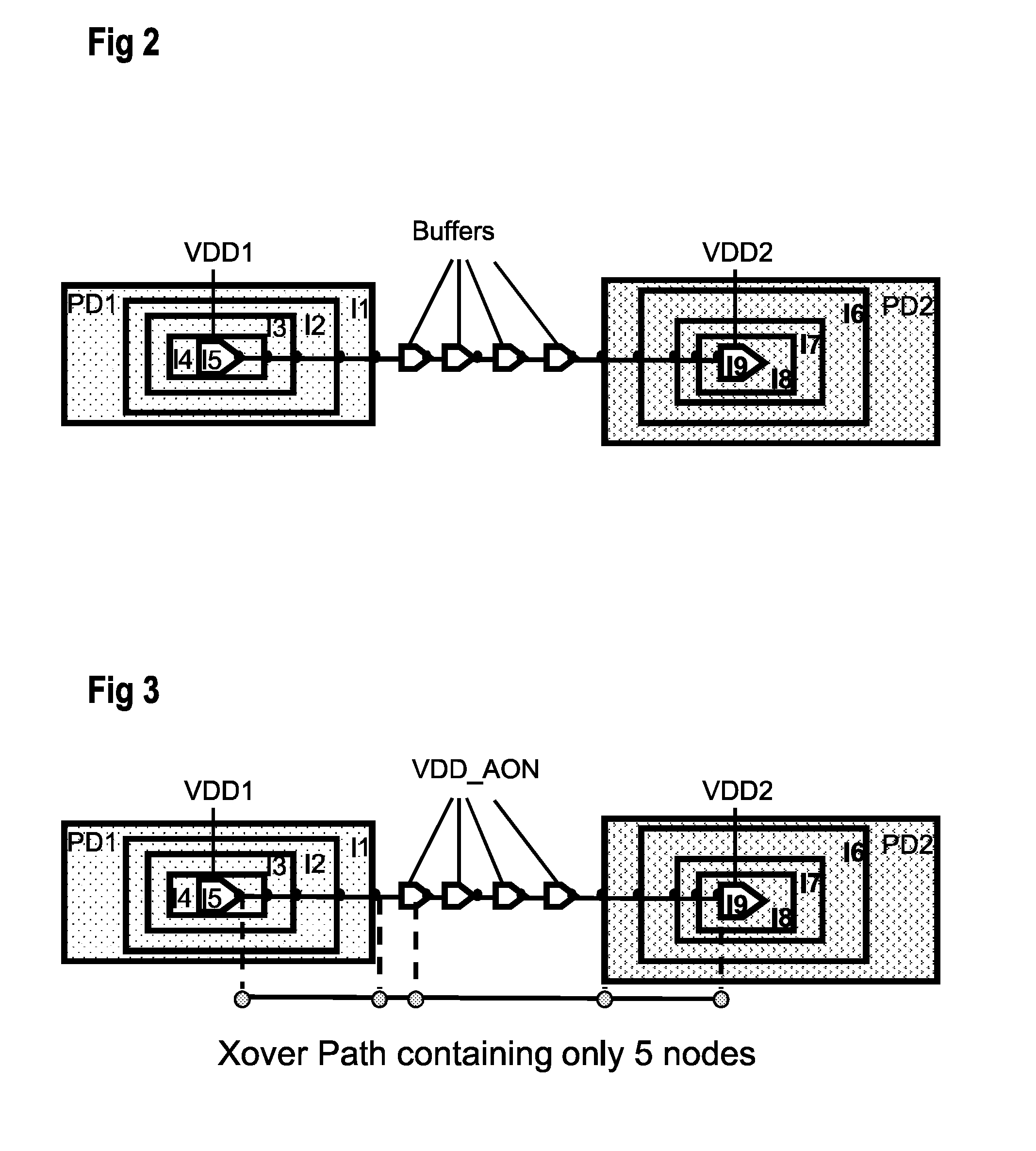
Checking transitions between two adjacent power domains is usually not sufficient.
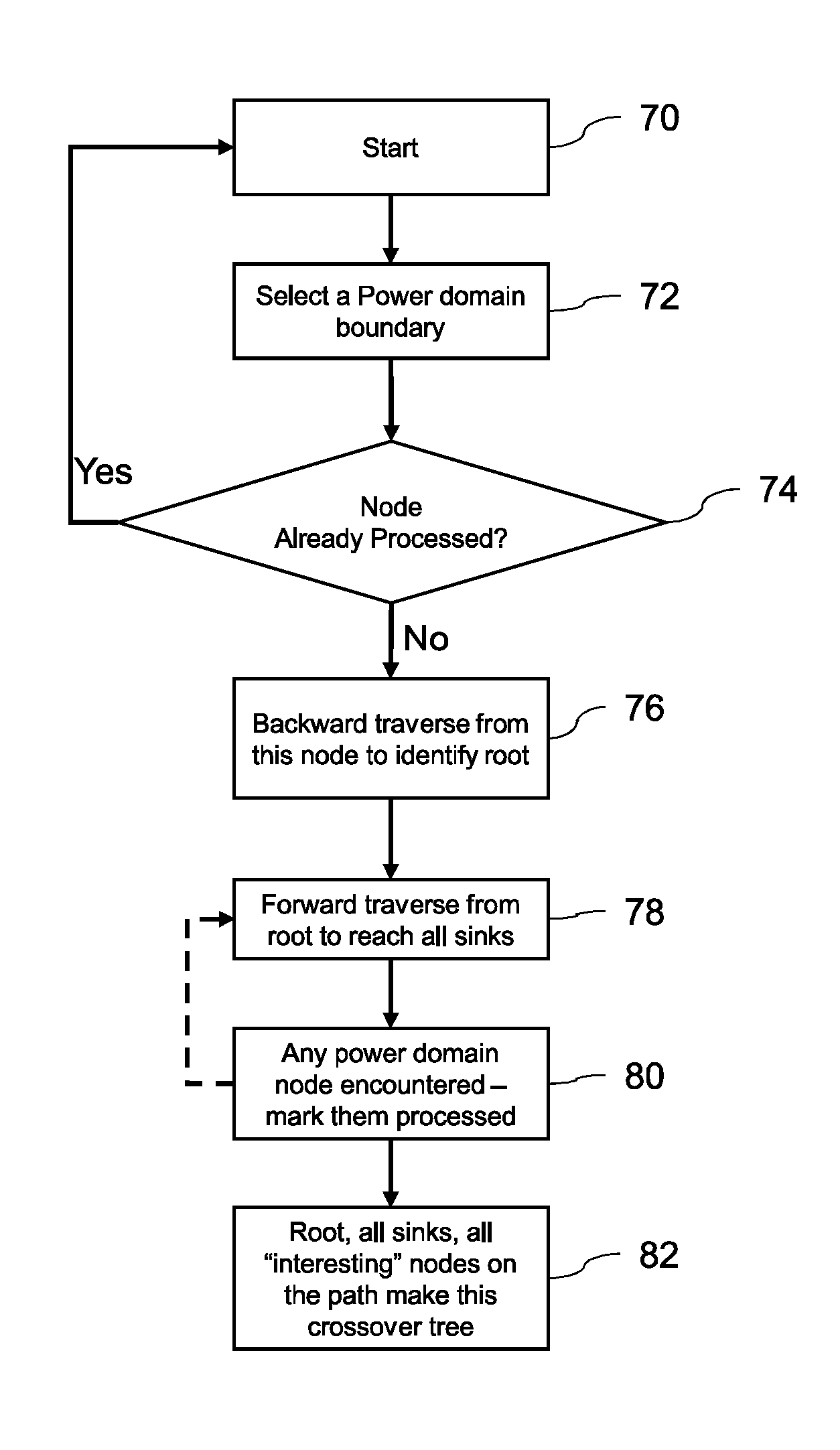
Analysis of all these crossover paths, with each path having large number of elements will be expensive in terms of runtime.
Searching through a large design, which e.g. includes tens of millions of logic gates or more, to find all these paths may be very expensive if it has to be done again and again.
In addition, this representation needs very low foot-print, that enable user to run the tool in machines with smaller amount of memory, instead of requiring to purchase very expensive machines with a large amount of memory.

Method used


Image

  • Low Power Verification Method for a Circuit Description and System for Automating a Minimization of a Circuit Description
  • Low Power Verification Method for a Circuit Description and System for Automating a Minimization of a Circuit Description
  • Low Power Verification Method for a Circuit Description and System for Automating a Minimization of a Circuit Description

Examples


Embodiment Construction

[0034]In one example embodiment, a Logic Gate comprises smallest building blocks in technology libraries using which the design is built. They are gates like buffer, inverter, AND gates, OR gates, flip-flops, latches, etc. In addition, a complex gate includes a logic Gate which is not buffer, inverter, isolation cell or level-shifter cell. Logic Blocks include design elements created by logic designers using Logic Gates and interconnections. Design is comprised of combinations and interconnection Logic Blocks. Logic Ports are ports that through these points Logic Blocks send or receive signals from other Logic Blocks. A Voltage Island or Voltage Domain includes a partition of the design which derives its power supply from a source not shared with another partition. Such a partition influences the interaction of electrical signals in a voltage island with those of another or among themselves. Such a partition also influences the stability of operation of a voltage island as voltage c...


PUM


Abstract

A method for low power verification of a circuit description comprises minimizing a circuit description by creating a plurality of crossover trees, and evaluating each of the plurality of crossover trees to identify circuit description errors, in particular low power circuit description errors. The minimizing may comprise creating a plurality of crossover trees to represent circuit description, wherein each crossover tree has a unique set of selected ports and gates of the circuit description.

Description

BACKGROUND[0001]1. Field[0002]This disclosure relates to the art of electronic design automation (EDA), and more specifically to an automated design process and chip description system.[0003]2. Related Art[0004]Battery life is a critical factor for success of a mobile product. Hence every silicon chip now provides low power functionality as a method to extend the battery life. Low power functionality may be provided in practice by shutting down part of the chip to save leakage power and designing the chip to have multiple voltage domains where different domains can operate at different power states to provide either performance (at the price of high power consumption) or low power consumption (with a lower level of performance).[0005]When a chip has multiple functional blocks, many of the blocks can be switched off or while other blocks can be powered at a variety of different power levels. Clearly, at any instance, the number of possible combinations of different functional blocks ...

Claims


Application Information

Patent Timeline
Patent Type & Authority Applications(United States)
IPC IPC(8): G06F17/50
CPCG06F17/5045G06F17/5081G06F30/3323G06F2119/06G06F30/398G06F30/30
Inventor SENAPATI, DIPTI RANJANDE, KAUSHIKMUKHERJEE, RAJARSHIRAMACHANDRA, SHREEDHAR
Owner SYNOPSYS INC
Learn More