
Large three-way joint die forging device for power station equipment and die forging method thereof

A three-way, large-scale technology, used in forging/pressing/hammer devices, driving devices of forging presses, mechanical equipment, etc., can solve the problems that are not suitable for mass production, unqualified die forging products, and heavy machining drilling workload. and other problems, to achieve the effect of improving the efficiency and competitiveness of enterprises, reducing the amount of machining, and shortening the production cycle.

Inactive Publication Date: 2020-08-25
SHANGHAI DIANJI UNIV
View PDF7 Cites 4 Cited by
  • Summary
  • Abstract
  • Description
  • Claims
  • Application Information

AI Technical Summary

Problems solved by technology

[0004] When the free forging method is used to forge the whole Y-shaped tee, the material utilization rate is low, resulting in a great waste of materials, and increases the production cost, and the production cycle is also long, which is not suitable for mass production
[0005] When die forging is used to forge the whole Y-shaped tee, if no insert is set on the Y-shaped branch, the workload of machining and drilling in the later stage will be large; if the insert is set to extend into the mold, due to the high temperature of the metal Due to the fluidity problem, the metal may not flow perfectly according to the preset state and fill the gap between the insert and the inner wall of the mold during extrusion, nor can it form a cylindrical hole in the shape of the insert, resulting in unqualified forged products

Method used


Image

  • Large three-way joint die forging device for power station equipment and die forging method thereof
  • Large three-way joint die forging device for power station equipment and die forging method thereof
  • Large three-way joint die forging device for power station equipment and die forging method thereof

Examples


Embodiment 1

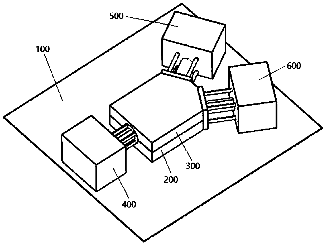
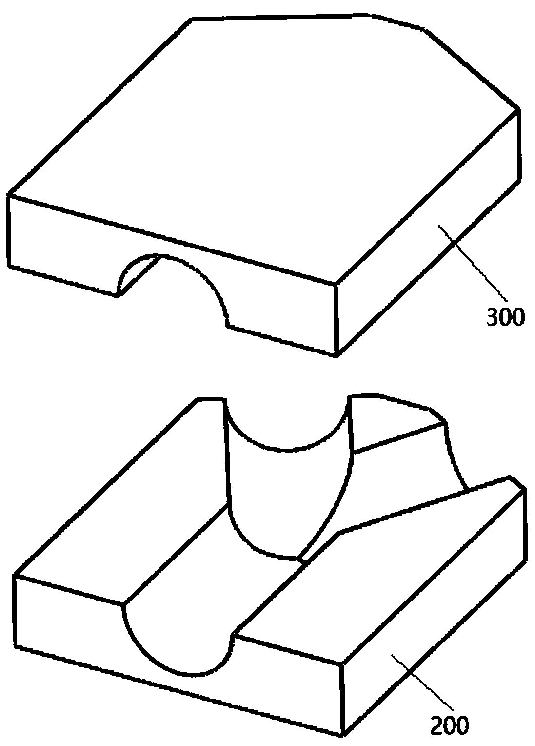
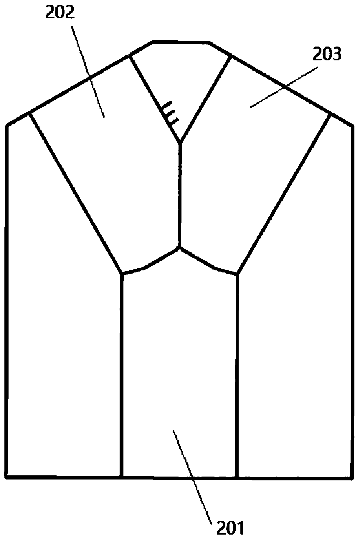
[0039] Embodiment 1: as Figure 1 to Figure 7 As shown, a large-scale three-way die forging device for power station equipment proposed by the present invention includes a bottom plate 100 , a lower die 200 , and an upper die 300 . The lower mold 200 includes a main cavity 201, a first branch cavity 202 and a second branch cavity 203, all of which are semi-cylindrical. The structure of the upper mold 300 corresponds to the lower mold 200, and the lower mold 200 and the upper mold 300 are enclosed After forming a chamber for forming large Y-shaped tees.

[0040] The bottom plate 100 is connected with a main road propulsion device 400, a first branch road blocking device 500, and a second branch road blocking device 600, the first branch road blocking device 500 and the second branch road blocking device 600 have the same structure, and respectively It corresponds to the first branch cavity 202 and the second branch cavity 203 .

[0041] Wherein, the trunk propulsion device 40...

Embodiment 2

[0045] Embodiment 2 is further designed on the basis of Embodiment 1. The blocking plate 503 is provided with a pressure sensor for detecting the pressure on the blocking plate 503, and the pressure sensor can sense the pressure changes at multiple positions of the blocking plate 503 around the plug 504, And the pressure signal can be transmitted to the host computer for processing, and the pressure sensor in the embodiment is the prior art, which will not be repeated here; in addition, in this embodiment, several pressure sensors can be provided and distributed around the plug 504 .

[0046] And the side walls of the first branch cavity 202 and / or the second branch cavity 203 of the lower mold 200 are provided with several scale lines. In this embodiment, the first branch cavity 202 is selected to set three scale lines.

[0047] Due to the different materials of different metal materials, the fluidity of the metal in the molten state is different. Therefore, when the blocking...

Embodiment 3

[0048] Embodiment 3, a die forging method of a large-scale three-way die forging device for power station equipment, comprising the following steps:

[0049] Step 1, preparatory work, the trunk main engine box 401 in the trunk propulsion device 400 operates and drives four trunk hydraulic push rods 402, trunk push plates 403, and punches 404 to withdraw from the main cavity 201; the first Both the branch blocking device 500 and the second branch blocking device 600 drive the corresponding plug 504 to separate from the first branch cavity 202 and the second branch cavity 203 , and remove the upper mold 300 .

[0050] Step 2: Start working, heat the cylindrical metal blank material to be extruded to 1200 degrees Celsius in a heating furnace, and then place it in the main cavity 201 of the lower mold 200 by clamping it.

[0051] Step 3: The upper mold 300 is fastened to the lower mold 200, and the top of the upper mold 300 is pressed by an external press, and the main road host b...


PUM


Abstract

The invention discloses a large three-way joint die forging device for power station equipment and a die forging method thereof. The key point of the technical scheme is as follows: the large three-way joint die forging device for power station equipment comprises a bottom plate, a lower die and an upper die wherein the lower die comprises a main cavity, a first branch cavity and a second branch cavity, the main cavity, the first branch cavity and the second branch cavity are semi-cylindrical, the upper die corresponds to the lower die in structure, and the lower die and the upper die are encircled to form a chamber for forming a large Y-shaped three-way joint; the bottom plate is connected to a trunk propelling device, a first branch blocking device and a second branch blocking device, and the first branch blocking device and the second branch blocking device are consistent in structure and correspond to the first branch cavity and the second branch cavity, separately. The large three-way joint die forging device improves the percent of pass of forged large Y-shaped three-way joints, shortens the production period while improving the reliability, lowers the operation cost of the equipment and improves the enterprise benefit and competitiveness.

Description

technical field [0001] The invention relates to the field of die forging of large tees, in particular to a large tee die forging device for power station equipment and a die forging method thereof. Background technique [0002] The large Y-shaped tee is one of the very important core components in the current thermal power generation and nuclear power generation systems. Its functions are, for example, used to transmit and divert high-temperature and high-pressure water vapor. With the continuous development of my country's power generation industry, the demand for large-scale tees is increasing. In addition to ensuring excellent performance, the requirements for tees are also higher and higher for processing cycle and production costs. Require. [0003] The current large-scale Y-shaped tee products mainly include two production methods: free forging and die forging. The free forging method is generally to use a large hydraulic press for free forging combined with machining...

Claims


Application Information

Patent Timeline
Patent Type & Authority Applications(China)
IPC IPC(8): B21J5/02B21J13/02B21J9/02B21J9/12B21J1/06B21K1/16
CPCB21J1/06B21J5/02B21J9/02B21J9/12B21J13/02B21K1/16
Inventor 牛龙江辛绍杰杨杰张栋刘钊曹峰华
Owner SHANGHAI DIANJI UNIV
Learn More