
Surface treatment method of die steel after molding

A processing method and technology of die steel, applied in the direction of manufacturing tools, grinding machines, grinding machine parts, etc., can solve the problems of inability to ensure sufficient contact of the surface of die steel, increase the operating cost of manufacturers, wear the surface of die steel, etc., to save operation. Cost, easy cleaning, guaranteed thorough results

Active Publication Date: 2020-08-25
浙江利源重工科技有限公司
View PDF23 Cites 0 Cited by
  • Summary
  • Abstract
  • Description
  • Claims
  • Application Information

AI Technical Summary

Problems solved by technology

[0003] a. When cleaning the oxide layer, the cleaning brush is often driven to reciprocate on the surface of the mold steel by automated equipment or manually to peel the oxide layer from the surface of the mold steel. Since the bristles on the cleaning brush are in a fixed position, it is impossible to ensure that the mold steel Every part of the surface is in full contact with the bristles, which is prone to incomplete cleaning;
[0004] b. After the cleaning brush has been used for a long time, the oxide layer debris peeled off from the surface of the mold steel is easy to adhere to the bristles, so it is necessary to clean the bristles in time or replace the cleaning brush regularly. Frequent replacement of the cleaning brush will inevitably increase the operation of the manufacturer The cost and economy are poor, and when cleaning the bristles, due to the large number of bristles and small diameter, it is difficult to completely remove the debris on the bristles with conventional cleaning tools, and the remaining debris will be cleaned in the subsequent oxide layer During the process, it moves synchronously with the cleaning brush, thereby wearing down the surface of the mold steel

Method used


Image

  • Surface treatment method of die steel after molding
  • Surface treatment method of die steel after molding
  • Surface treatment method of die steel after molding

Examples


Embodiment Construction

[0037] The embodiments of the present invention will be described in detail below with reference to the accompanying drawings, but the present invention can be implemented in many different ways defined and covered by the claims.

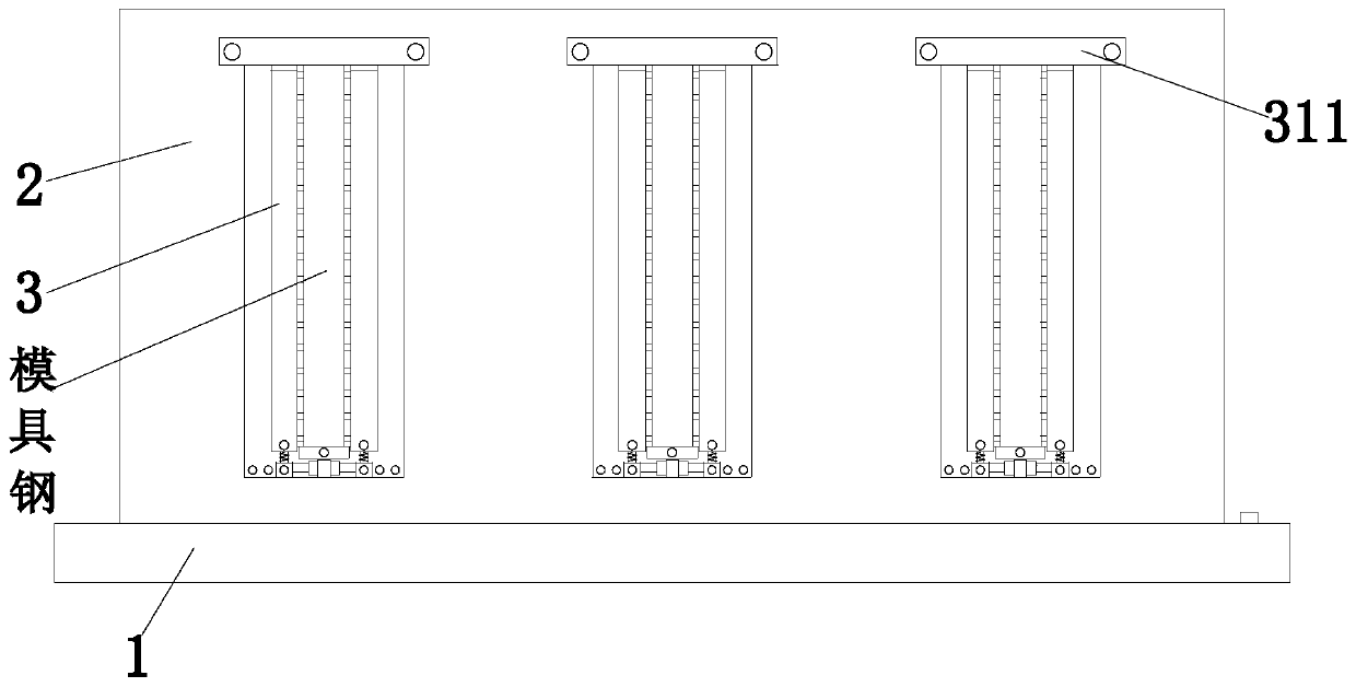
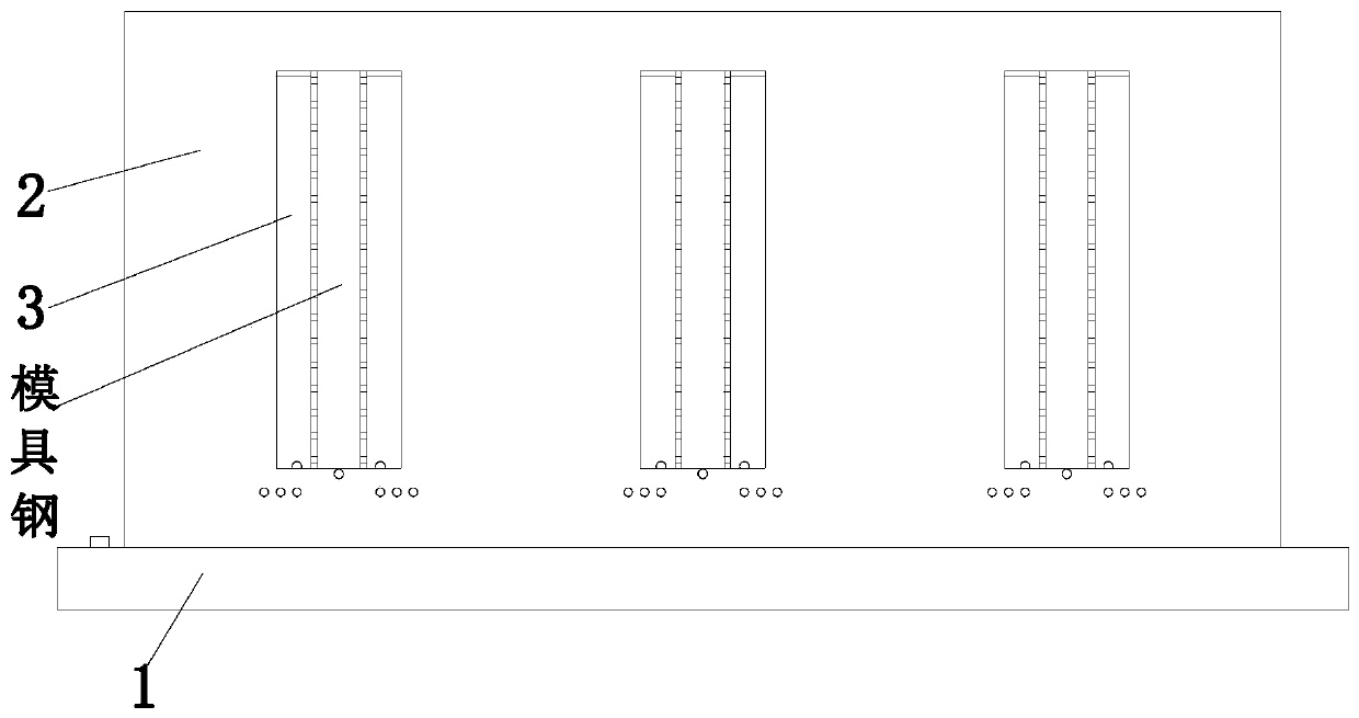
[0038] Such as Figure 1 to Figure 9 As shown, a method for surface treatment of mold steel after forming uses a kind of oxide layer cleaning equipment. The oxide layer cleaning equipment includes a substrate 1, a shell 2 and a cleaning device 3. The specific process for cleaning the scale is as follows:

[0039] S1. Equipment adjustment: Adaptively adjust the position of the corresponding structure of the device according to the thickness of the mold steel;

[0040] S2. mold steel transmission: the mold steel to be cleaned is delivered to the cleaning device 3 one by one;

[0041] S3. oxide layer cleaning: the oxide layer on the surface of the model steel is cleaned by the cleaning device 3;

[0042] S4. Material discharge: take out the cleaned mo...


PUM


Abstract

The invention relates to a surface treatment method of die steel after molding. Oxide layer cleaning equipment is used and comprises a base plate, a shell and a cleaning device. The specific technological process for cleaning oxide skins on the surface of the die steel by adopting the oxide layer cleaning equipment comprises the following steps of equipment adjustment, die steel transferring, oxide layer cleaning, discharging and fragment collecting. The cleaning device comprises cleaning branch chains, connecting blocks, moving frames, telescopic rods, rotating cams, rotating rods and rotating motors, and the cleaning branch chains comprise top plates, extrusion blocks, cleaning brushes, linkage plates and inserting frames. According to the surface treatment method of the die steel aftermolding, the cleaning brushes can be driven to move back and forth in multiple directions during cleaning, so that the purposes of expanding cleaning ranges and reducing cleaning dead angles are achieved, the cleaning brushes are of detachable combination structures, and the cleaning brushes with long-time use are convenient to clean and parts are convenient replace.

Description

technical field [0001] The invention relates to the technical field of die steel surface treatment, in particular to a surface treatment method for mold steel after forming. Background technique [0002] Die steel is a type of steel used to make molds such as cold stamping dies, hot forging dies, and die-casting dies. In the production process of die steel, the surface will form an oxide film-iron oxide scale due to oxidation, and the oxide layer needs to be cleaned before it is put into use. The following questions: [0003] a. When cleaning the oxide layer, the cleaning brush is often driven to reciprocate on the surface of the mold steel by automated equipment or manually to peel the oxide layer from the surface of the mold steel. Since the bristles on the cleaning brush are in a fixed position, it is impossible to ensure that the mold steel Every part of the surface is in full contact with the bristles, which is prone to incomplete cleaning; [0004] b. After the clea...

Claims


Application Information

Patent Timeline
Patent Type & Authority Applications(China)
IPC IPC(8): B24B27/033B24B41/04B24B41/06B24B47/04B24B55/12
CPCB24B27/033B24B41/04B24B41/06B24B47/04B24B55/12
Inventor 黄美英吕宁李玮
Owner 浙江利源重工科技有限公司
Learn More