
Multistage devolatilization device for nylon 6 melt

A devolatilization device and melt technology, applied in the field of nylon materials, can solve the problems of affecting the production efficiency of PA6, increase in melt viscosity, pipeline blockage, etc., and achieve the effects of high speed, low oligomer content, and reduced content.

Active Publication Date: 2020-08-25
ZHEJIANG HENGYI PETROCHEMICAL RES INST CO LTD
View PDF4 Cites 2 Cited by
  • Summary
  • Abstract
  • Description
  • Claims
  • Application Information

AI Technical Summary

Problems solved by technology

However, to achieve a large amount of hot water extractables removal, the device needs to have a higher devolatilization area and vacuum degree, and under this high-efficiency devolatilization, the molecular weight of nylon 6 will increase rapidly, and the melt viscosity will increase significantly lead to molding difficulties
In addition, how to collect volatiles, avoid pipeline blockage, and effectively reuse volatiles also affects PA6 production efficiency

Method used


Image

  • Multistage devolatilization device for nylon 6 melt
  • Multistage devolatilization device for nylon 6 melt
  • Multistage devolatilization device for nylon 6 melt

Examples


Embodiment 1

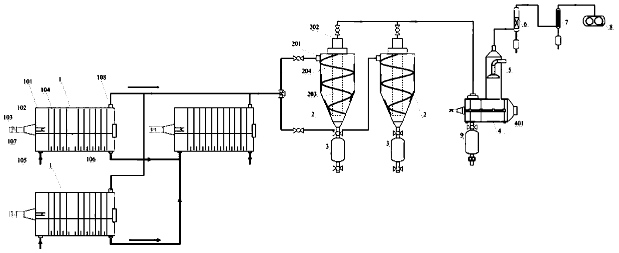
[0053] A nylon 6 melt multi-stage devolatilization device includes a devolatilization system and a component collection system connected in sequence.

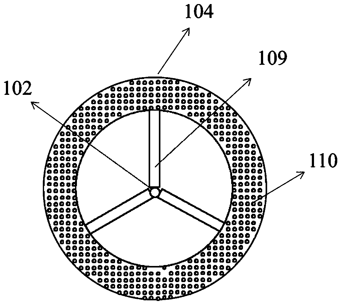
[0054] Among them, such as image 3 As shown, the devolatilization system includes two front and rear devolatilization reactors 1 connected in series; the devolatilization reactor includes a shell 101, a hollow shaft 102, a motor 103, and eleven devolatilizer plates 104; the shell The bottom of the shell is provided with a melt inlet 105 and a melt outlet 106. The middle of the side of the shell is provided with a gas inlet 107, and the top of the shell is provided with a gas outlet 108 (the melt inlet and the melt outlet, the gas inlet and the gas outlet are all located at Opposite side); the hollow shaft is horizontally arranged in the housing and one end of the hollow shaft is connected with the gas inlet, and the motor is used to drive the hollow shaft to rotate; figure 1 As shown, the devolatilizer disk is fixed on the hollow...

Embodiment 2

[0065] A nylon 6 melt multi-stage devolatilization device includes a devolatilization system and a component collection system connected in sequence.

[0066] Among them, such as image 3 As shown, the devolatilization system includes two parallel devolatilization reactors 1 and a devolatilization reactor connected in series with the aforementioned two devolatilization reactors in parallel; each of the devolatilization reactors includes a shell 101 , Hollow shaft 102, motor 103 and eleven devolatilizer plates 104; the bottom of the shell is provided with a melt inlet 105, a melt outlet 106, the middle of the side of the shell is provided with a gas inlet 107, the top of the shell is provided There is a gas outlet 108 (the melt inlet and the melt outlet, the gas inlet and the gas outlet are all located on opposite sides); the hollow shaft is horizontally arranged in the shell and one end is connected to the gas inlet, and the motor is used to drive the hollow shaft The shaft rota...


PUM


Abstract

The invention relates to the field of nylon materials, and discloses a multistage devolatilization device for nylon 6 melt. The multistage devolatilization device comprises a devolatilization system and a component collection system which are connected in sequence, wherein the devolatilization system comprises a plurality of devolatilization reaction kettles which are connected in series and / or inparallel; each devolatilization reaction kettle comprises a shell, a hollow rotating shaft, a motor and a devolatilization disc, the hollow rotating shaft is horizontally arranged in the shell, one end of the hollow rotating shaft communicates with a gas inlet, the devolatilization disc is fixed on the hollow rotating shaft, air holes are distributed in the devolatilization disc, and a gas outletof the devolatilization reaction kettle is connected with the component collection system; and the component collecting system comprises a high-boiling-point component removing unit and a low-boiling-point component removing unit which are connected in sequence. According to the invention, efficient devolatilization can be carried out on the nylon 6 melt, the polycondensation reaction of nylon 6can be inhibited in the devolatilization process, influence on a spinning forming process due to the sudden increase of the molecular weight of the nylon 6 under a vacuum condition is avoided, time isprovided for nylon 6 amide exchange, molecular weight distribution is narrowed, and melt quality is improved.

Description

Technical field [0001] The invention relates to the field of nylon materials, in particular to a nylon 6 melt multi-stage devolatilizer. Background technique [0002] The conversion rate of caprolactam hydrolysis polymerization is generally about 90%, which means that about 10% of caprolactam monomers and oligomers (also called hot water extractables) remain in the polymer. The monomers account for about 75%. About 25%), the impurities in these melts have a great influence on spinning. Therefore, before PA6 spinning, the chips need to be extracted. According to FZ / T51004-2011, the hot water extractable content of PA6 chips should be less than 0.5wt% (high-quality product). Nowadays, continuous hot water extraction technology is widely used in industry to extract monomers and oligomers in PA6 chips, so that the extractable content in chips is less than 0.5wt%, which meets the requirements of high-speed spinning. However, a large amount of water and energy are consumed in the pro...

Claims


Application Information

Patent Timeline
Patent Type & Authority Applications(China)
IPC IPC(8): C08G69/46C08G69/14B01D3/10B01D3/30B01D11/04B01D7/02B01D5/00
CPCC08G69/46C08G69/14B01D3/106B01D3/30B01D3/146B01D11/0492B01D11/0488B01D7/02B01D5/003B01D5/0036B01D5/006B01D5/0045B01D5/0096B01D2011/007
Inventor 徐锦龙王松林汤廉黄家鹏何宁艳王华平王朝生
Owner ZHEJIANG HENGYI PETROCHEMICAL RES INST CO LTD
Learn More