
Overflow loss recovery system based on hydraulic motor and control method for overflow loss recovery system

A hydraulic motor and recovery system technology, applied in fluid pressure actuation system components, fluid pressure actuation system testing, servo motors, etc. Differential loss and other problems, to achieve the effect of solving the differential pressure loss of the overflow valve port, solving the differential pressure loss of the valve port, and efficient energy recovery

Active Publication Date: 2020-08-25
HUAQIAO UNIVERSITY
View PDF5 Cites 0 Cited by
  • Summary
  • Abstract
  • Description
  • Claims
  • Application Information

AI Technical Summary

Problems solved by technology

[0003] The Chinese invention patent with the publication number CN106122188B discloses a conventional overflow valve overflow loss recovery and reuse system based on hydraulic accumulators, which is a system designed by the applicant in the early stage, which uses hydraulic accumulators as energy storage Although the element can solve the overflow loss problem of the overflow element itself under certain conditions, since the pressure of the accumulator cannot be actively controlled, in the proportional overflow valve whose target pressure will be dynamically adjusted, the pressure difference at the overflow valve port It cannot be set according to the minimum pressure difference, and there is still a certain pressure loss at the valve port, which makes it difficult to achieve efficient energy recovery

Method used


Image

  • Overflow loss recovery system based on hydraulic motor and control method for overflow loss recovery system
  • Overflow loss recovery system based on hydraulic motor and control method for overflow loss recovery system

Examples


Embodiment Construction

[0029] The invention will be further explained below in conjunction with specific embodiments:

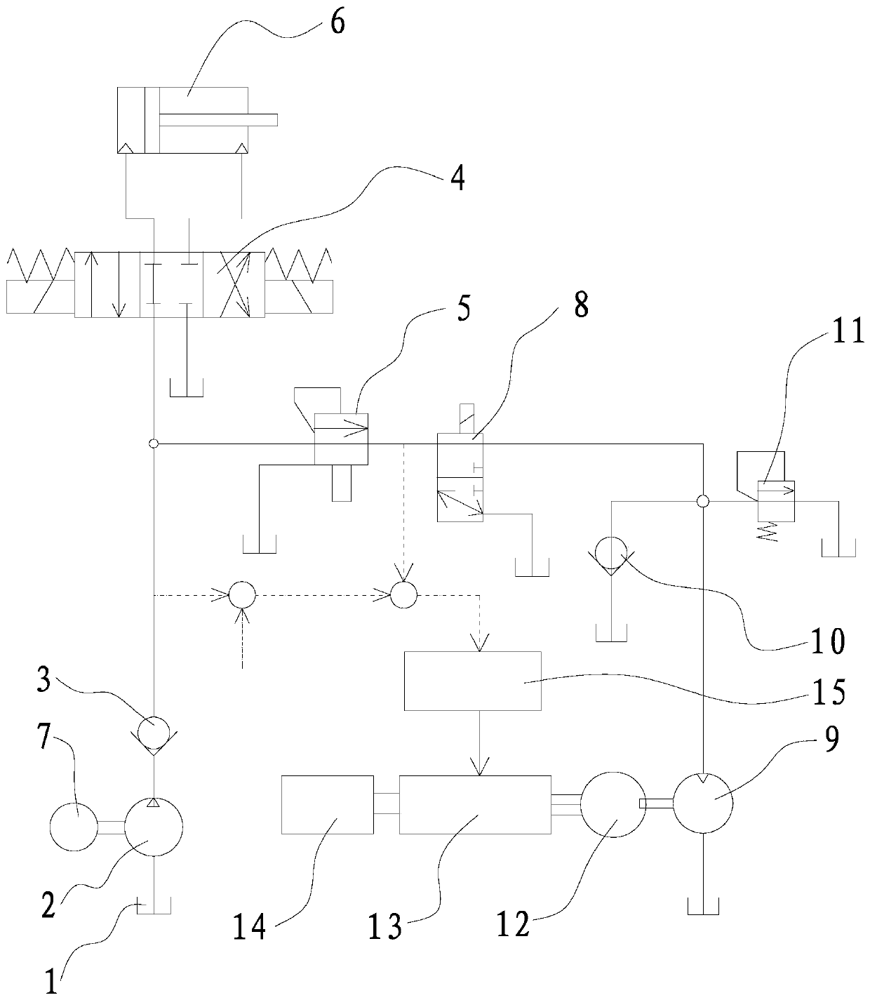
[0030] Such as figure 1 As shown, this embodiment provides an overflow loss recovery system based on a hydraulic motor, which includes an oil tank 1, a main pump connected to an oil inlet and an oil tank 2, an oil inlet connected to an oil outlet of the main pump 2. The first reversing valve 4 and the first relief valve 5 connected to the oil outlet of the first check valve 3 and the oil inlet port respectively, and the hydraulic cylinder 6 connected to the first reversing valve 4. Among them, the main pump 2 can be a fixed pump or a variable pump, which can be selected according to actual needs; the main pump 2 is driven by a drive motor 7. Specifically, the input shaft of the main pump 2 and the output shaft of the drive motor 7 are connected through a coupling. Shaft connection. In addition, all the valves mentioned in this embodiment are solenoid valves.

[0031] The first reversi...


PUM


Abstract

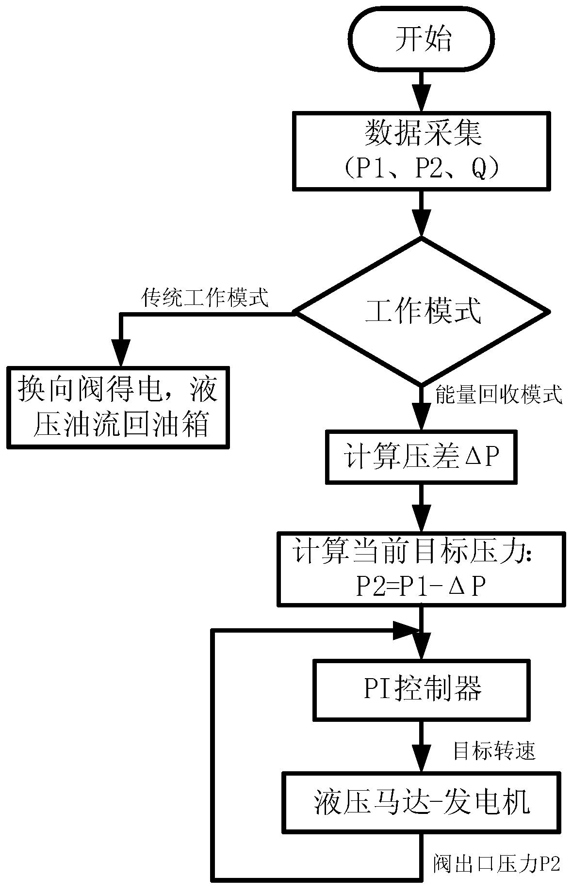
The invention provides an overflow loss recovery system based on a hydraulic motor. The overflow loss recovery system comprises an oil tank, a main pump, a first one-way valve, a first reversing valve, a first overflow valve and a hydraulic cylinder, wherein the first overflow valve is provided with a first valve oil outlet and a pilot oil outlet, the first valve oil outlet is connected with a second reversing valve, the second reversing valve is provided with second oil outlets and a second oil inlet, one of the second oil outlets is connected with a hydraulic motor, and the hydraulic motor is in transmission connection with a generator. The invention further provides an overflow loss recovery control method based on the hydraulic motor. Through the organic combination effect on the reversing valves, the overflow valves, the one-way valves, the hydraulic motor, the generator and the like, overflow loss energy recovery for overflow valve openings is realized, hydraulic energy lost by the outlets of the overflow valves is converted into electric energy through the hydraulic motor and the generator, thus energy recovery is realized, meanwhile, the generator can realize active control, thus differential pressure loss of the valve openings can be solved, and efficient energy recovery is realized.

Description

Technical field [0001] The invention relates to an energy-saving control system and a control method thereof, in particular to a hydraulic motor-based overflow loss recovery system and a control method thereof. Background technique [0002] The outlet of the proportional relief valve (conventional) is generally connected to the fuel tank, and the relief valve works, and its valve port pressure loss is the inlet pressure of the relief valve. The greater the relief pressure level, the greater the valve port pressure loss, and the overflow The flow rate varies with the type of hydraulic system. With the trend of high-pressure hydraulic system, the overflow loss problem will become more serious. The overflow loss of the overflow valve is related to the type of hydraulic system, the actual working conditions in the working process and the operation mode of the operator. According to the function of the overflow valve, the overflow loss is mainly divided into pressure regulating overf...

Claims


Application Information

Patent Timeline
Patent Type & Authority Applications(China)
IPC IPC(8): F15B21/14F15B21/08F15B11/18F15B13/04F15B19/00
CPCF15B21/14F15B21/08F15B11/18F15B13/04F15B19/00Y02E10/20
Inventor 林添良苏玲缪骋叶月影李钟慎任好玲陈其怀付胜杰郭桐
Owner HUAQIAO UNIVERSITY
Learn More