Solid-state light source light-emitting device

A technology for light-emitting devices and solid-state light sources, which can be applied to light sources, electric light sources, lighting devices, etc., and can solve the problems of low luminous efficiency, low color rendering index of output light, and insufficient blue light.

Pending Publication Date: 2020-08-25
赫尔曼友瀚范贝赫库姆 +1
View PDF11 Cites 4 Cited by
  • Summary
  • Abstract
  • Description
  • Claims
  • Application Information

AI Technical Summary

Problems solved by technology

[0004] The technical problem to be solved by the present invention is: the luminous efficiency of the existing light-emitting devices is not high and the blue light is usually insufficient, and at the same time the red light output by the existing light-emitting devices is insufficient and the color rendering index of the output light is generally relatively low

Method used


Image

  • Solid-state light source light-emitting device
  • Solid-state light source light-emitting device
  • Solid-state light source light-emitting device

Examples


Embodiment 1

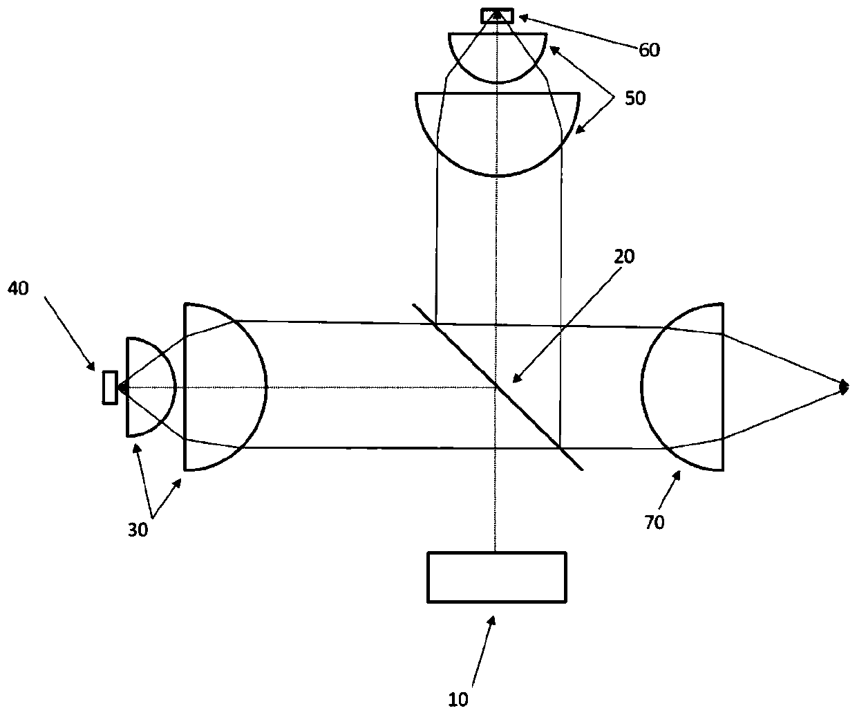
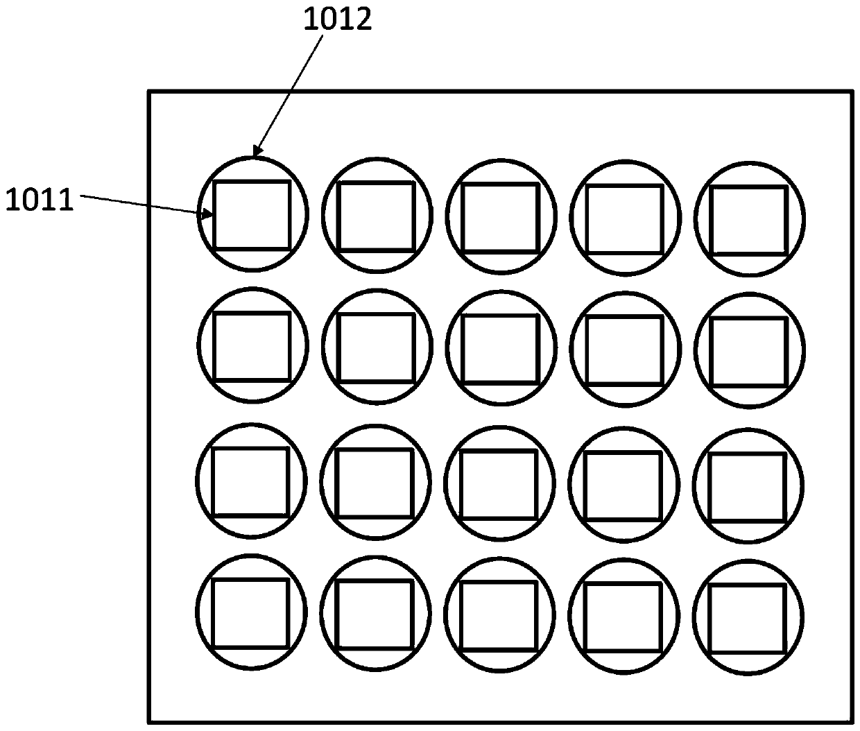
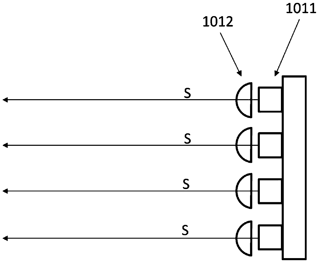
[0110] Such as Figure 5 As shown, the first laser light source 101 is provided with a blue light (central wavelength is 460nm) laser and a collimating lens, wherein the light emitting direction and polarization direction of all lasers are the same, when the first laser light source 101 is placed, the polarization of the light emitted by it is The direction relative to the incident plane of the polarizing beam splitter 102 is S polarized light, so the first laser light source 101 can emit nearly parallel blue light (the center wavelength is 460nm) and shoot to the polarizing beam splitter 102, and these light rays include The incident surface of the beam splitter 102 is the light of S polarized light. Here the polarizing beam splitter 102 is selected to be a narrow-band (440-470nm) polarizing cube beam splitter. For blue light (the center wavelength is 460nm), the polarizing beam splitter 102 can reflect the S polarized light and transmit the P polarized light. For the wavelen...

Embodiment 2

[0114] Such as Figure 6 As shown, the difference between this embodiment and Embodiment 1 is that the polarizing beam splitter 102 selected in this embodiment is a flat plate rather than a cube, and it is lighter than a cube-shaped polarizing beam splitter, so that the whole device can be made Less weight. Other structures and working methods of this embodiment are the same as those of Embodiment 1.

Embodiment 3

[0116] Such as Figure 7 As shown, the difference between this embodiment and Embodiment 2 lies in the selection of the polarizing beam splitter 102 . Here, the polarizing beam splitter 102 is selected as a narrowband (440-470nm) polarizing beam splitter. For blue light (center wavelength is 460nm), the polarizing beam splitter 102 can reflect the S polarized light and transmit the P polarized light. For visible light with a wavelength longer than 470nm The light (such as green light) can be reflected by the polarizing beam splitter 102 . When the laser light source 101 is placed, the polarization direction of the emitted light is P-polarized relative to the incident plane of the polarizing beam splitter 102, and the polarizing beam splitter 102 transmits the incident P-polarized light to the first optical path.

[0117] In the first optical path, the polarization beam splitter 102 transmits the P-polarized blue light (the center wavelength is 460nm) to the wave plate 103. He...


PUM


Abstract

The invention provides a solid-state light source light-emitting device which is characterized by comprising a first laser light source, a polarization beam splitter, a wave plate, a first light condensation element, a first wavelength conversion device, a dichroscope, a third-color light generation part and a light condensation part. The solid-state light source light-emitting device has the advantages of being high in brightness, small in optical expansion amount, high in color rendering index, uniform in light spot, long in service life, high in efficiency and the like. The solid-state light source light-emitting device can be applied to systems requiring high illumination intensity and small optical expansion, such as entertainment lighting systems, projection systems, automobile lighting systems, medical lighting systems, searchlighting lighting systems, field operation lighting systems, navigation lighting systems, portable lighting systems and the like.

Description

technical field [0001] The invention belongs to the field of lighting, in particular to the field of solid-state light source lighting. The solid-state light source lighting device provided by the present invention can be applied to systems that require high light intensity and small etendue, such as entertainment lighting systems, projection systems, automotive lighting systems, medical lighting systems, search lighting systems, and field work lighting systems, marine lighting systems, portable lighting systems, etc. Background technique [0002] As an ideal point light source, laser has the advantages of small etendue, long life and no mercury. Using it as a light source to excite the fluorescent powder can produce colored light or white light, and at the same time cooperate with the use of optical elements to obtain an ideal light-emitting device with a small etendue. figure 1 It is a structural schematic diagram of a light emitting device in the prior art. Such as fi...

Claims


Application Information

Patent Timeline
Patent Type & Authority Applications(China)
IPC IPC(8): F21S2/00F21K9/64F21K9/69F21V9/30F21V9/45F21V5/04G02B27/28G02B27/10G02B27/09F21Y115/10
CPCF21S2/00F21K9/64F21K9/69F21V9/30F21V9/45F21V5/04G02B27/283G02B27/1006G02B27/286G02B27/0938F21Y2115/10
Inventor 赫尔曼·友瀚·范·贝赫库姆郑华
Owner 赫尔曼友瀚范贝赫库姆
Why Eureka
Try Eureka