Fiber grating sensor multifunctional testing device and method

A grating sensor, multi-functional testing technology, applied in the direction of measuring devices, instruments, etc., can solve the problems that the temperature of the fiber grating sensor cannot be quantitatively changed, there is no popular application, and the fiber grating sensor cannot be applied, etc., to achieve simple structure, convenient operation, small size effect

Active Publication Date: 2020-08-25
NORTHWEST UNIV(CN)
View PDF6 Cites 0 Cited by
  • Summary
  • Abstract
  • Description
  • Claims
  • Application Information

AI Technical Summary

Problems solved by technology

The main reason why the temperature strain test of the fiber grating sensor is not carried out at the same time is that the temperature test of the fiber grating sensor is usually carried out in a constant temperature water bath or a blast drying box, and it is impossible to apply a quantitative stress to the fiber grating sensor to make it happen. Equivalent strain; or when the FBG sensor is doing strain testing, the temperature of the FBG sensor cannot be quantitatively changed
[0003] As a new type of sensor, the fiber grating sensor has not been widely used in the engineering field, so the device that can simultaneously measure the temperature and strain of the fiber grating sensor has not been reported in papers or sold. Strain (displacement, tension) test device

Method used


Image

  • Fiber grating sensor multifunctional testing device and method
  • Fiber grating sensor multifunctional testing device and method
  • Fiber grating sensor multifunctional testing device and method

Examples


Embodiment 1

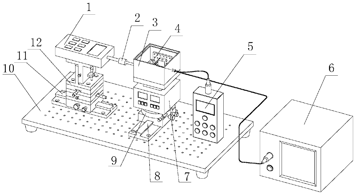
[0036] exist figure 1 Among them, the fiber Bragg grating sensor multifunctional testing device of the present embodiment is composed of a push-pull force meter 1, a sensor connector 2, a heat preservation cover 3, a sensor holder 4, a temperature measuring instrument 5, a fiber grating demodulation device 6, a constant temperature heater 7, The second rack and pinion translation platform 8, the rotary lifting platform 9, the optical platform 10, the first rack and pinion translation platform 11, and the three-dimensional combination translation platform 12 are connected to form.

[0037]On the left side of the optical table 10, a first rack-and-pinion translation stage 11 is installed, and a second rack-and-pinion translation stage 8 is installed on the right side. The first rack-and-pinion translation stage 11 is used for left-right adjustment, and the second rack-and-pinion translation stage 8 is used for front and rear adjustment, and the three-dimensional combined transla...

Embodiment 2

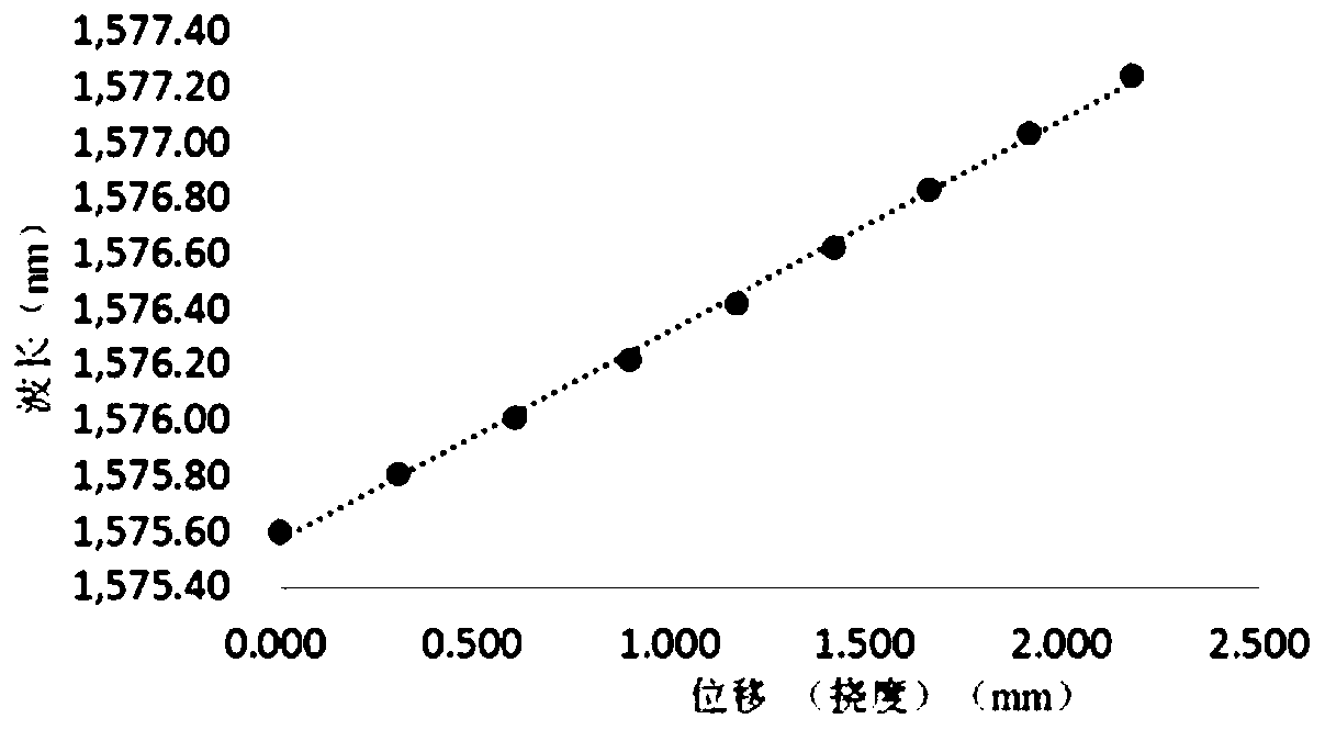
[0049] In this embodiment, the test device of Embodiment 1 is used to carry out the displacement sensing test on the optical fiber grating sensor with the cantilever structure of equal strength beryllium copper as the cantilever material. The specific test method includes the following steps:

[0050] S1. Install the fiber grating sensor to be tested and the sensor connector 2

[0051] a. Fix the fiber grating sensor to be tested on the sensor holder 4, and cover the heat preservation cover 3;

[0052] b. Adjust the vertical displacement screw micrometer sleeve of the three-dimensional combined translation stage 12, so that the sensor connector 2 located at the front end of the push-pull force meter 1 is at the same height as the free end stress point of the cantilever beam of the fiber grating sensor to be tested, and adjust the first gear The rack and pinion translation stage 11 and the second rack and pinion translation stage 8 make the sensor connector 2 roughly aligned wi...

Embodiment 3

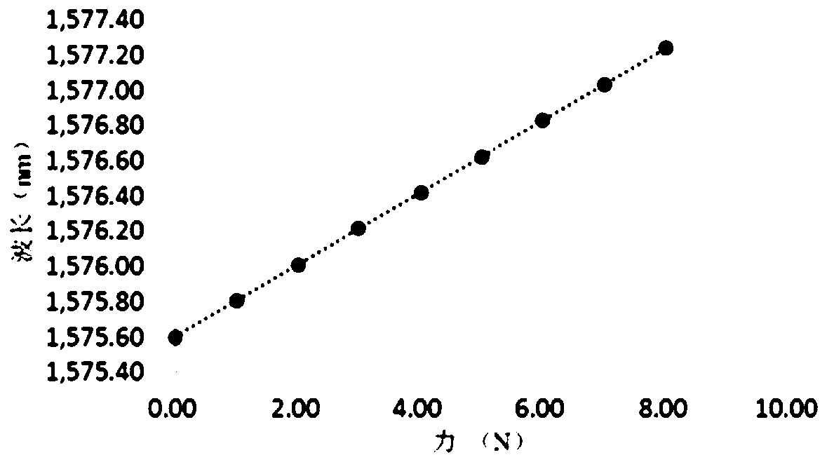
[0060] In this embodiment, the test device of Embodiment 1 is used to carry out the stress sensing test on the fiber grating sensor with the cantilever structure of equal strength beryllium copper as the cantilever material. The specific test method includes the following steps:

[0061] S1. Install the fiber grating sensor to be tested and the sensor connector 2

[0062] a. Fix the fiber grating sensor to be tested on the sensor holder 4, and cover the heat preservation cover 3;

[0063] b. Adjust the vertical displacement screw micrometer sleeve of the three-dimensional combined translation stage 12, so that the sensor connector 2 located at the front end of the push-pull force meter 1 is at the same height as the free end stress point of the cantilever beam of the fiber grating sensor to be tested, and adjust the first gear The rack and pinion translation stage 11 and the second rack and pinion translation stage 8 make the sensor connector 2 roughly aligned with the force p...


PUM


Abstract

The invention discloses a multifunctional testing device and method for a fiber grating sensor. The device is characterized in that an optical platform is provided with a strain force application mechanism and a sensor heating mechanism, wherein the strain force application mechanism is a three-dimensional combined translation platform disposed on a first gear rack translation platform, the three-dimensional combined translation platform is provided with a push-pull force meter, the push-pull force meter is provided with a sensor connector, according to the sensor heating mechanism, a rotary lifting table is arranged on a second gear rack translation table, a constant-temperature heater is arranged on the rotary lifting table, a heat preservation cover is arranged on a heating flat plate,a sensor fixer is arranged on the heating flat plate in the heat preservation cover, one side of the optical platform is provided with a thermodetector and a fiber bragg grating demodulation device, and a probe of the thermodetector is arranged in an insulation cover. The device is advantaged in that the device can be used for testing the temperature, displacement, tension and strain single-parameter sensing performance of a fiber bragg grating sensor, can further be used for testing the temperature and displacement or tension or strain double-parameter sensing performance at the same time, and has properties of simple structure, small size, convenience in operation, low energy consumption and multifunctional testing.

Description

technical field [0001] The invention belongs to the technical field of optical fiber grating sensors, and in particular relates to a multifunctional testing device and method for optical fiber grating sensors. Background technique [0002] Fiber Bragg grating sensors have attracted much attention in the field of optical fiber sensing due to their advantages of anti-electromagnetic interference, small size, light weight, corrosion resistance, and easy realization of wavelength division, time division and space division multiplexing. In recent years, there have been many reports on the application of fiber grating sensors in civil engineering, public transportation, military, aerospace, medical and other fields. Fiber Bragg grating sensor uses the change of fiber grating with external physical quantities, such as temperature and strain changes, which will cause the central wavelength shift of fiber grating reflection spectrum or transmission spectrum. The measurement of physic...

Claims


Application Information

Patent Timeline
Patent Type & Authority Applications(China)
IPC IPC(8): G01D18/00G01D21/02
CPCG01D18/00G01D21/02
Inventor 冯德全乔学光罗小东白燕
Owner NORTHWEST UNIV(CN)
Why Eureka
Try Eureka