Digital holographic particle measuring device and method based on diaphragm spatial modulation

A space modulation and digital holography technology, applied in measuring devices, optical devices, particle and sedimentation analysis, etc., can solve the problems of overlapping, low measurement accuracy of high-concentration particle fields, and poor real-time performance, so as to reduce mutual superposition and interference, realize real-time reconstruction and processing, and reduce the effect of calculation

Pending Publication Date: 2020-08-25
ZHEJIANG UNIV
View PDF0 Cites 2 Cited by
  • Summary
  • Abstract
  • Description
  • Claims
  • Application Information

AI Technical Summary

Problems solved by technology

However, laser beams and area array cameras are widely used to measure particle size by digital holographic technology at present. The hologram recorded in this way contains three-dimensional data. The data volume is large, and the processing speed is slow and difficult during reconstruction, resulting in real-time measurement. not good
In the case of a high-concentration particle field, there are relatively dense particles on the holographic optical path, and the measured particle hologram has the problem of overlapping and interference between particles, which brings great difficulties to data processing processes such as hologram reconstruction and particle identification. It is a great inconvenience, resulting in low measurement accuracy of high-concentration particle fields

Method used


Image

  • Digital holographic particle measuring device and method based on diaphragm spatial modulation
  • Digital holographic particle measuring device and method based on diaphragm spatial modulation
  • Digital holographic particle measuring device and method based on diaphragm spatial modulation

Examples


Embodiment Construction

[0041] In order to make the technical means, creative features, work flow field and usage method of the present invention easy to understand, the specific implementation of the present invention will be further described below in conjunction with the accompanying drawings.

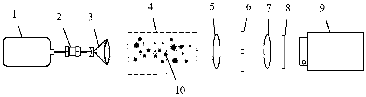
[0042] Such as figure 1 As shown, the digital holographic particle measurement device based on aperture spatial modulation provided by the present invention includes a laser light source 1, a spatial filter 2, a beam expander 3, a measurement area 4, a convex lens 5, an aperture 6, a convex lens 7, and an optical filter 8. Digital camera9. The above-mentioned components are located on the same axis according to the arrangement order, and are in the form of coaxial holography, and are fixed and adjusted by optical guide rails.

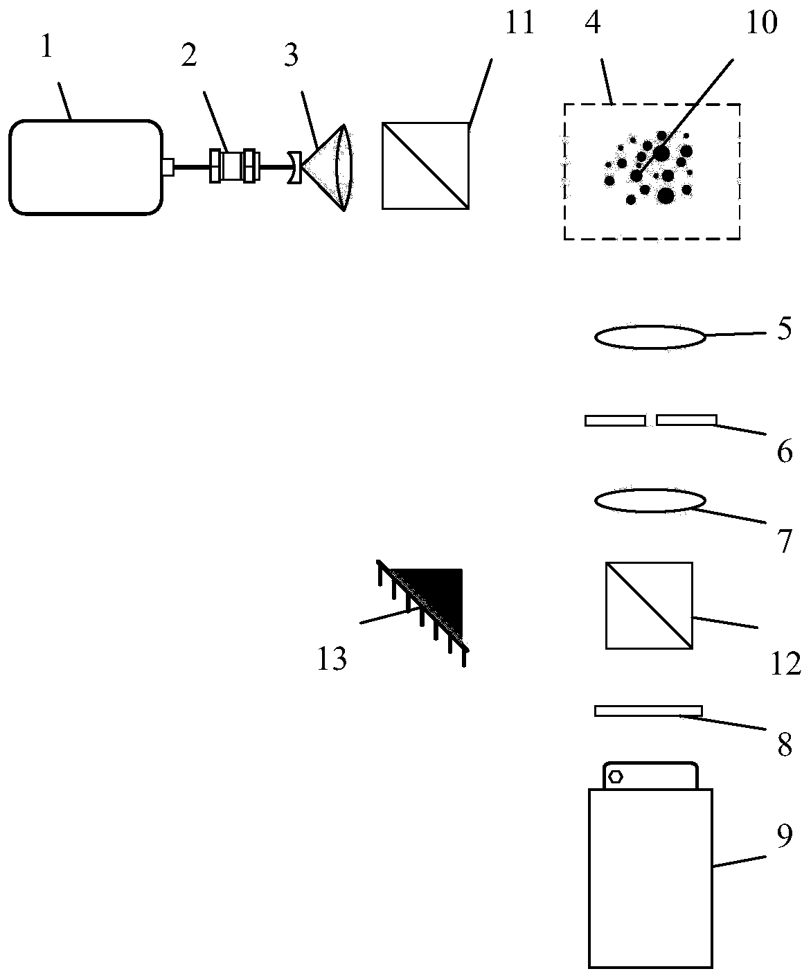
[0043] Such as figure 2 As shown, the aperture modulation unit and the image recording unit are arranged perpendicular to the laser axis, and a part of the reference light is ext...


PUM

PropertyMeasurementUnit
Seam widthaaaaaaaaaa

Abstract

The invention discloses a digital holographic particle measuring device based on diaphragm spatial modulation. The device comprises a laser light source; a spatial filter and a beam expander, including a spatial filter and a beam expander; a measuring area, particles to be measured being distributed in the measuring area; adiaphragm modulation unit comprising a first lens, a diaphragm and a secondlens through which the object light passes in sequence; an image recording unit comprising a CCD or CMOS digital camera; and a data processing unit. The invention also discloses a digital holographicparticle measurement method based on diaphragm spatial modulation. The method comprises the following steps: generating a collimated light beam by using the laser light source and the spatial filtering and beam expanding unit to irradiate a particle field of a measurement area; carrying out spatial modulation on the particulate matter light by adopting a diaphragm modulation unit; recording a holographic interference fringe image of the particles by using a CCD or CMOS digital camera; and reconstructing and analyzing the recorded particle holographic interference fringe image to obtain particle information. The device and the method provided by the invention can realize rapid monitoring of the particle size of the particles and reduce mutual overlapping and interference among the particles.

Description

technical field [0001] The invention relates to the field of particle field measurement by advanced optical methods, in particular to a digital full-particle measurement device and method based on aperture space modulation. Background technique [0002] Particles play an important role in energy, materials, chemical industry, environment, aerospace and other industries. Solid particles such as pulverized coal particle transportation and combustion in coal-fired power plants, fluidized bed particle circulation, etc., liquid particles such as internal combustion engine spray combustion, liquid rocket engine atomization mixed combustion propulsion, etc., bubble particles such as boiling heat and mass transfer, turbine Leaf cavitation, etc. The research on particles has great scientific significance and broad industrial application prospects. Accurate measurement of key parameters such as particle position and particle size is of great significance for efficient and safe produc...

Claims


Application Information

Patent Timeline
IPC IPC(8): G01N15/02G01B9/021G01B11/00
CPCG01B9/021G01B11/00G01N15/02G01N15/0227G01N2015/0233G01N2015/0238
Inventor 吴学成吴迎春姚龙超曾磊陈玲红高翔邱坤赞岑可法
Owner ZHEJIANG UNIV
Why Eureka
Try Eureka