Frequency-adjustable ultralow-frequency mechanical antenna structure

An antenna structure and ultra-low frequency technology, applied in the field of ultra-low frequency communication, can solve the problems of insufficiency of electromagnetic wave frequency and large volume of ultra-low frequency, achieve the effect of light weight, meet the requirements of frequency, and reduce the weakening of magnetic induction intensity

Active Publication Date: 2020-08-25
DALIAN JIAOTONG UNIVERSITY
View PDF9 Cites 11 Cited by
  • Summary
  • Abstract
  • Description
  • Claims
  • Application Information

AI Technical Summary

Problems solved by technology

[0005] At present, on the basis of solving the problem of large volume of the existing ultra-low frequency, in order to further solve the problem that the frequency of the electromagnetic wave excited by the mechanical antenna is limited by the speed of the motor, the frequency of the electromagnetic wave cannot meet the frequency requirements in actual communication. The present invention discloses a frequency-adjustable ultra-low frequency Mechanical antenna structure, a frequency-adjustable ultra-low frequency mechanical antenna structure, including a static magnetic field generating module that generates a static magnetic field and a cutting static magnetic field module that cuts the static magnetic field generating module to generate an electromagnetic field that varies with time

Method used


Image

  • Frequency-adjustable ultralow-frequency mechanical antenna structure
  • Frequency-adjustable ultralow-frequency mechanical antenna structure
  • Frequency-adjustable ultralow-frequency mechanical antenna structure

Examples


Embodiment Construction

[0026] In order to make the technical solutions and advantages of the present invention more clear, the technical solutions in the embodiments of the present invention are clearly and completely described below in conjunction with the drawings in the embodiments of the present invention:

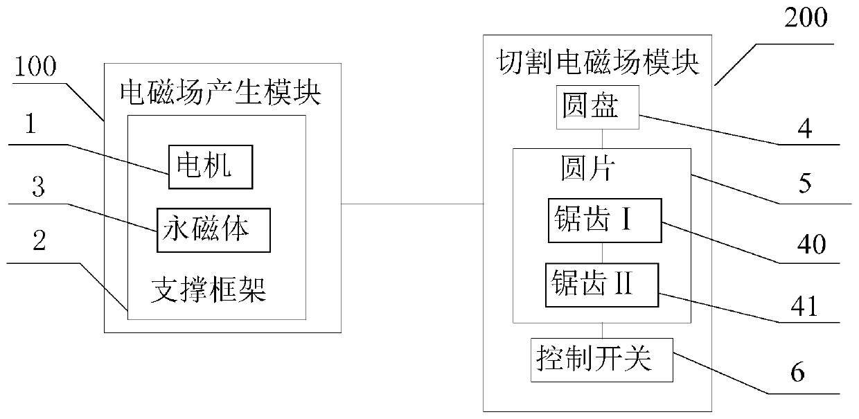
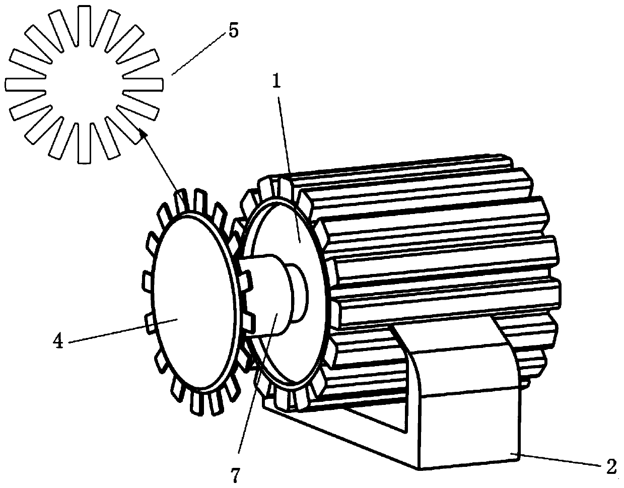
[0027] figure 1 It is a block diagram of the present invention; figure 2 It is a structural schematic diagram of the present invention; a frequency-adjustable ultra-low frequency mechanical antenna structure, including a static magnetic field generating module 100 for generating a static magnetic field and a cutting static magnetic field module 200 for cutting the static magnetic field generating module 100 to generate an electromagnetic field that varies with time .

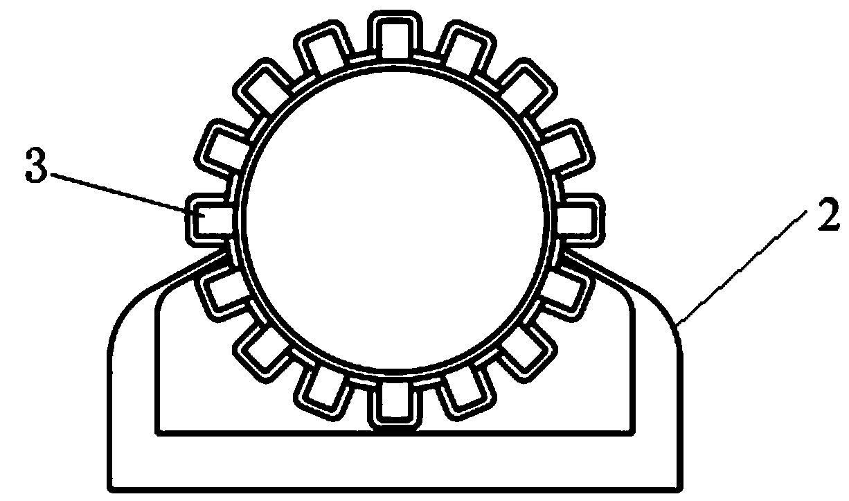
[0028] image 3 It is a side view of the electromagnetic field generation module of the present invention; the static magnetic field generation module 100 includes a motor 1, a plurality of permanent magnets 3, a support fr...


PUM


Abstract

The invention discloses a frequency-adjustable ultra-low frequency mechanical antenna structure and belongs to the technical field of ultra-low frequency communication. The antenna structure comprisesa static magnetic field generation module for generating a static magnetic field and a static magnetic field cutting module for cutting the static magnetic field generation module to generate an electromagnetic field changing with time, and the static magnetic field generation module comprises a motor, a plurality of permanent magnets and a supporting frame for fixing the rotating motor and the plurality of permanent magnets; the supporting frame is arranged outside the motor; the plurality of permanent magnets are uniformly arranged on the outer surface of the supporting frame; the static magnetic field cutting module comprises a disc, a wafer with sawteeth and a control switch for controlling the sawtooth length change of the wafer and driving the wafer to move; the number of teeth of the sawtooth wafer is the ratio of the time-varying magnetic field frequency to the working frequency of the rotating motor, and by changing the mechanical motion mode, the frequency of electromagneticwaves generated by a mechanical antenna is improved while the weakening of the magnetic induction intensity is reduced as much as possible, so that the requirement for the frequency in the transmission process is met.

Description

technical field [0001] The invention relates to the technical field of ultra-low frequency communication, in particular to a frequency-adjustable ultra-low frequency mechanical antenna structure. Background technique [0002] In September 2017, the US DARPA (Defense Advanced Research Projects Agency) launched a 45-month "mechanical antenna" program, which intends to drive electret or permanent magnet materials through mechanical devices to generate radio frequency signals for transmission. This method can greatly reduce the volume and power consumption of the transmitting antenna of the low-frequency navigation communication system, and realize a major transformation and subversive innovation of the radio transmitting system. Seek to use the advantages of ultra-low frequency (SLF) radio waves to achieve strategic ultra-long-range and penetrating communication, so as to overcome the shortcomings of traditional antenna communication methods, such as too large infrastructure an...

Claims


Application Information

Patent Timeline
Patent Type & Authority Applications(China)
IPC IPC(8): H01Q1/36H01Q5/28
CPCH01Q1/36H01Q5/28Y02D30/70
Inventor 王晓煜张雯厚周鑫曹振新全鑫
Owner DALIAN JIAOTONG UNIVERSITY
Why Eureka
Try Eureka