Digital coding holographic antenna and regulation and control method thereof

A holographic antenna and digital coding technology, applied in antennas, resonant antennas, antenna arrays, etc., can solve the problems of inaccurate holographic pattern recording, large changes in slot radiation characteristics, serious boundary reflection, etc. The unit radiation performance is stable, which is conducive to the effect of low cost

Pending Publication Date: 2020-08-25
SOUTH CHINA UNIV OF TECH +1
View PDF14 Cites 8 Cited by
  • Summary
  • Abstract
  • Description
  • Claims
  • Application Information

AI Technical Summary

Problems solved by technology

In 2007, according to the uniqueness theorem of the electromagnetic field, P.Sooriyadevan realized the recording of holographic patterns by placing metal strips at the minimum point of the interference field to simulate the boundary conditions of the ideal electric wall, but this holographic structure only records the interference field The minimum value of the holographic pattern is not accurate enough, and the restored object wave has a large error with the original wave.
However, the r

Method used


Image

  • Digital coding holographic antenna and regulation and control method thereof
  • Digital coding holographic antenna and regulation and control method thereof
  • Digital coding holographic antenna and regulation and control method thereof

Examples


Embodiment

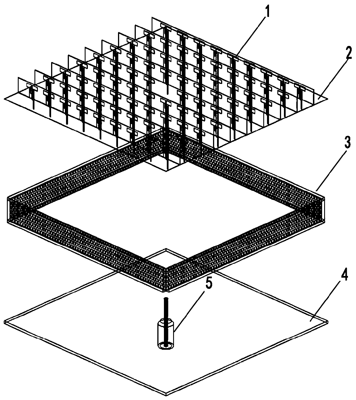
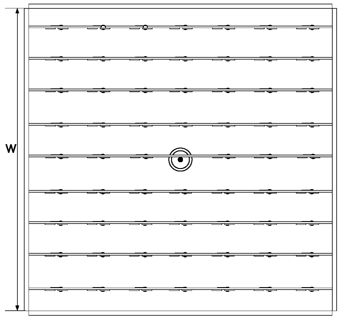
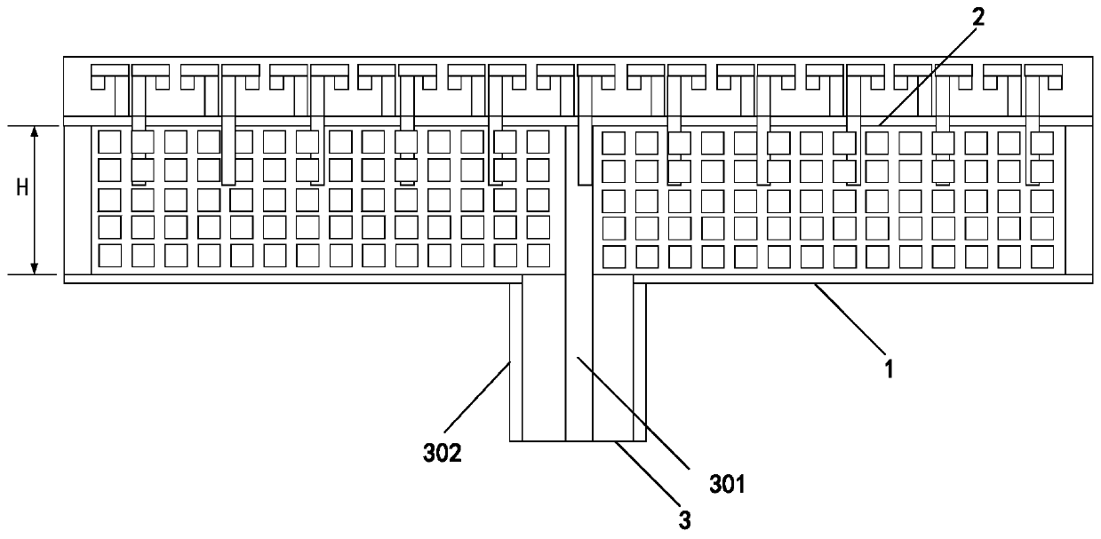
[0036] Such as figure 1 , figure 2 and image 3 As shown, a digitally coded holographic antenna includes a control circuit and a radial waveguide. The radial waveguide includes a top metal plate 2 and a bottom metal plate 4. In this embodiment, the radial waveguide is rectangular, and in the rectangular radial waveguide The supermaterial absorbing boundary 3 is loaded around, that is, the space between the top metal plate and the bottom metal plate is surrounded by the metamaterial absorption boundary, forming a rectangular cavity with the top metal plate and the bottom metal plate.

[0037] Dipole radiation unit 1 is loaded on the upper surface of the top metal plate, and a circular hole with a diameter of 0.6 mm is etched in the middle of the top metal plate, and a probe with a length of 2 mm is inserted into the radial waveguide for Coupling radial electromagnetic wave energy to excite the unit to radiate.

[0038] The length of the probe is about one-fifth equivalent w...


PUM


Abstract

The invention discloses a digital coding holographic antenna and a regulation and control method thereof. The device comprises a control circuit and a radial waveguide, and the radial waveguide comprises a top metal plate and a bottom metal plate. A dipole radiation unit is loaded on the upper surface of the top metal plate; metamaterial absorption boundaries are loaded on the periphery of the radial waveguide, the radial waveguide, the top metal plate and the bottom metal plate form a cavity, the bottom metal plate is provided with a coaxial feed structure, the dipole radiation unit is a dipole unit array, each dipole unit is loaded with a radio frequency switch, and the radio frequency switches are connected with a control circuit.

Description

technical field [0001] The invention relates to the technical field of holographic antennas, in particular to a digitally coded holographic antenna and a control method thereof. Background technique [0002] The holographic principle originated from physical optics, which refers to the use of a holographic structure to record the interference fringes formed by the coherence of the reference wave and the object wave to obtain a holographic structure, and then irradiate the holographic structure with the reference wave to diffract the object wave. Compared with the traditional film that can only record the light intensity, the holographic structure can record the intensity and phase information of the object wave at the same time, so it can realize the reproduction of the object image. [0003] Unlike the many materials that can record beam interference information in the optical field, recording materials in the microwave field has always been a difficult problem, which has h...

Claims


Application Information

Patent Timeline
IPC IPC(8): H01Q9/28H01Q1/36H01Q1/38H01Q1/50H01Q15/00H01Q21/06
CPCH01Q9/285H01Q1/36H01Q1/38H01Q1/50H01Q15/0026H01Q15/0086H01Q21/062
Inventor 章秀银姚逸慧徐慧俊杨波伍尚坤高永振高霞
Owner SOUTH CHINA UNIV OF TECH
Why Eureka
Try Eureka