
System for three-dimensional image reconstruction and positioning analysis in CT cabin of puncture surgical robot

A surgical robot and three-dimensional imaging technology, applied in surgical navigation systems, image analysis, surgical robots, etc., can solve problems such as high operating environment requirements, high prices, and complicated calibration processes, achieving high robustness, ensuring puncture accuracy, The effect of ensuring the success rate of one-time puncture

Pending Publication Date: 2020-09-01
苏州新医智越机器人科技有限公司
View PDF7 Cites 10 Cited by
  • Summary
  • Abstract
  • Description
  • Claims
  • Application Information

AI Technical Summary

Problems solved by technology

[0002] CT-guided percutaneous lung biopsy uses tracking technology for positioning on the basis of CT images and completes patient registration. During the operation, it can display real-time puncture guidance information for doctors, simulate the position of the needle tip, and guide doctors to perform puncture according to the planned path. In recent years, the surgical navigation system based on electromagnetic navigation and optical positioning has been applied in percutaneous lung biopsy. And calculate more than two images of the same target point, so as to obtain the position of the measured object. The optical positioning system is a positioning system with high positioning accuracy in the market, but it has high requirements for the operating environment, the calibration process is complicated and the price is high. High, for this reason, we use the 3D image reconstruction and positioning analysis system in the CT cabin of the puncture surgery robot

Method used


Image

  • System for three-dimensional image reconstruction and positioning analysis in CT cabin of puncture surgical robot
  • System for three-dimensional image reconstruction and positioning analysis in CT cabin of puncture surgical robot
  • System for three-dimensional image reconstruction and positioning analysis in CT cabin of puncture surgical robot

Examples


Embodiment Construction

[0019] The following will clearly and completely describe the technical solutions in the embodiments of the present invention with reference to the accompanying drawings in the embodiments of the present invention. Obviously, the described embodiments are only some, not all, embodiments of the present invention. Based on the embodiments of the present invention, all other embodiments obtained by persons of ordinary skill in the art without making creative efforts belong to the protection scope of the present invention.

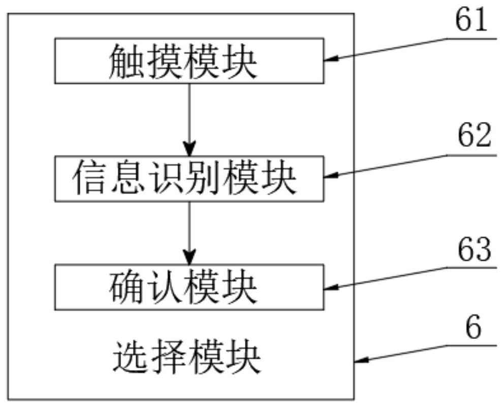
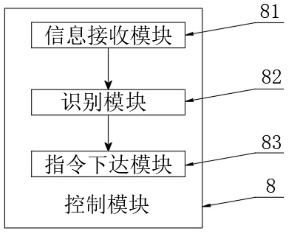
[0020] The present invention provides a technical solution: a system for three-dimensional image reconstruction and positioning analysis in the CT cabin of a puncture surgery robot, please refer to figure 1 , including a CT scanning machine 1, scanning through the CT scanning machine 1;

[0021] see figure 1 The electrical output of the CT scanner 1 is connected to the data reading module 2, and the data reading module 2 reads the data image, and then transmi...


PUM


Abstract

The invention discloses a three-dimensional image reconstruction and positioning analysis system used in a puncture surgery robot CT cabin in the technical field of CT-guided percutaneous lung puncture biopsy. The system includes a CT scanner; the CT scanner is in electrical output connection with a data reading module; a central processor is in electrical input connection with an electromagneticpositioning module and a path planning module; the central processor is in electrical output connection with an image processing module, a control module and a display module; and the control module is in electrical output connection with a puncture robot. According to the system, marking points are no longer placed on the body surface of a patient on hardware, but six marking points are fixed toa CT examination bed at the same time, and an improved D-H reverse motion algorithm is applied to the algorithm, so that a CT image guides the robot to conduct percutaneous lung puncture operation, the puncture precision can be well guaranteed through a positioning mechanism, especially the success rate of one-time puncture can be effectively guaranteed, and the system has high robustness.

Description

technical field [0001] The invention relates to the technical field of CT-guided percutaneous lung puncture biopsy, in particular to a three-dimensional image reconstruction and positioning analysis system in a CT cabin of a puncture surgery robot. Background technique [0002] CT-guided percutaneous lung biopsy uses tracking technology for positioning on the basis of CT images and completes patient registration. During the operation, it can display real-time puncture guidance information for doctors, simulate the position of the needle tip, and guide doctors to perform puncture according to the planned path. In recent years, the surgical navigation system based on electromagnetic navigation and optical positioning has been applied in percutaneous lung biopsy. And calculate more than two images of the same target point, so as to obtain the position of the measured object. The optical positioning system is a positioning system with high positioning accuracy in the market, but...

Claims


Application Information

Patent Timeline
Patent Type & Authority Applications(China)
IPC IPC(8): A61B10/02A61B6/03A61B34/10A61B34/20A61B34/30A61B90/11G06T7/00G06T7/70
CPCA61B10/0233A61B6/032A61B90/11A61B34/10A61B34/30A61B34/20G06T7/70G06T7/0012A61B2034/107A61B2034/2051G06T2207/10081G06T2207/30061
Inventor 牛福永李振晓乔飞
Owner 苏州新医智越机器人科技有限公司
Learn More