

Crude oil cleaning treatment method
A technology for clean treatment and crude oil, which is applied in the fields of hydrocarbon oil treatment products, treatment of hydrocarbon oil, and only multi-stage series refining process treatment. It can solve the problems of low cost, low recovery rate and poor environmental protection, and achieve stable operation of the treatment device. , the effect of qualified product quality
- Summary
- Abstract
- Description
- Claims
- Application Information
AI Technical Summary
Problems solved by technology
Method used
Image

Examples
Embodiment approach
[0036] In the present invention, the material of the main body of the vent tower 1 pipeline is 1Cr5Mo and 20#, and the above-mentioned materials require that the acid value of the material at the bottom of the vent tower 1 be less than or equal to 0.8mgKOH / g, and the acid value of the unpretreated crude oil is greater than or equal to 1mgKOH / g will have certain corrosiveness to the vent tower 1. According to an embodiment of the present invention, after the crude oil is pretreated, the first heavy component and the first mechanical impurities settle at the bottom of the vent tower 1 to form Slop oil, wherein the acid value of the slop oil is ≤0.5mgKOH / g. Therefore, in the present invention, the use of the delayed coker to process the clear crude oil will not cause corrosion to the vent tower 1 of the delayed coker, and can meet the requirements of the delayed coker.
[0037] In the present invention, impurities such as part of the chloride ions contained in the crude oil for c...
Embodiment 1
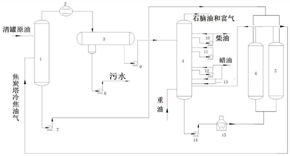
[0071] (a) the tank-cleaned crude oil containing moisture and impurities of 0.5% by weight is passed into the delayed coking unit (such as figure 1 Shown) in the vent tower 1, heavy oil is passed in the fractionation tower (4) with the flow rate of 240t / h (residue oil 227t / h, catalytic oil slurry 10t / h, deoiled asphalt 3t / h) simultaneously, total treatment The time is 87h;
[0072] (b) The first coke tower 5 is cut out, and the first coke tower 5 performs coke cooling in the coke tower. At the same time, the second coke tower 6 performs coke generation in the coke tower, and 2-3t / h steam is added to the coke tower 5 , carry out the first stage of cold coking for 1.5h, the first high-temperature oil gas produced and the third high-temperature oil gas produced when the second coke tower 6 is coking the coke tower are passed into the fractionation tower 4 together, and the temperature of the first high-temperature oil gas is about 400-420°C, the temperature of the third high-tem...
Embodiment 2
[0079] (a) the tank-cleaned crude oil containing moisture and impurities of 0.7% by weight is passed into a delayed coking unit (such as figure 1 Shown) in the vent tower 1, heavy oil is passed in the fractionation tower (4) with the flow rate of 230t / h (residue oil 205t / h, catalytic oil slurry 25t / h,) simultaneously, and the total treatment time is 120h;
[0080] (b) Cut out the first coke tower 5 to carry out coke cooling in the coke tower. At the same time, the second coke tower 6 carries out the coking of the coke tower, and adds 5t / h steam into the first coke tower 5 to carry out the first stage After cooling coke for 2 hours, the first high-temperature oil and gas produced together with the third high-temperature oil and gas generated during coke generation in the second coke tower 6 are passed into the fractionation tower 4. The temperature of the first high-temperature oil and gas is about 400-420°C. The temperature of the third high-temperature oil and gas is about 40...
PUM
| Property | Measurement | Unit |
|---|---|---|
| acid value | aaaaa | aaaaa |
| acid value | aaaaa | aaaaa |
| acid value | aaaaa | aaaaa |
Abstract
Description
Claims
Application Information