Multi-layer and multi-pass welding device and method based on visual representation

A multi-layer, multi-pass, welding device technology, applied in welding equipment, welding accessories, electrode support devices, etc., can solve the problems of low degree of automation, failure to achieve independent planning and intelligent control, and low efficiency.

Pending Publication Date: 2020-09-04
JILIN UNIV
View PDF0 Cites 17 Cited by
  • Summary
  • Abstract
  • Description
  • Claims
  • Application Information

AI Technical Summary

Problems solved by technology

[0003] (1) For each weld seam, the position of the welding torch and the position of the welding wire end point in the transverse direction of the weld seam and the depth direction of the weld seam need to be manually positioned and adjusted repeatedly. This process is low in automation and low in efficiency
[0004] (2) When each seam is welded, the walking path in the welding direction needs to be taught manually, and this process increases the welding man-hour
[0005] The traditional multi-layer multi-pass welding technology often fails to achieve independent path planning and intelligent control of the entire welding process. Therefore, welding workers propose a multi-layer multi-pass welding path planning technology: the main idea is to use equal cross-sectional area filling Strategies such as strategy and contour filling plan the position and posture of the welding torch in the subsequent welding process according to the cross-sectional shape of the unwelded weld groove, but this technology also has shortcomi...

Method used


Image

  • Multi-layer and multi-pass welding device and method based on visual representation
  • Multi-layer and multi-pass welding device and method based on visual representation
  • Multi-layer and multi-pass welding device and method based on visual representation

Examples


Embodiment Construction

[0087] The detailed content of the present invention and its specific implementation will be further described below in conjunction with the accompanying drawings.

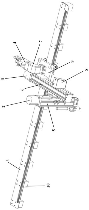
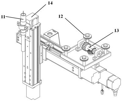
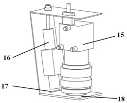
[0088] see Figure 1 to Figure 3 As shown, the multi-layer multi-channel welding device based on visual representation of the present invention includes a walking body, a walking guide rail, a 3D laser profile sensor, and a welding torch. The walking body is installed on the walking guide rail, and the 3D laser profile sensor 8 is installed in the walking body On the y-axis guide rail 6, the welding torch 11 is rigidly fixed on the output shaft of the welding torch pose control servo motor 14 in the walking body; the 3D laser profile sensor scans the weld seam to obtain the welding trajectory and the welding torch pose, and the rear device converts the welding trajectory The signal is converted into a corresponding electrical signal and transmitted to the execution motor of the walking body; the execution motor of...


PUM


Abstract

The invention relates to a multi-layer and multi-pass welding device and method based on visual representation, and belongs to the field of welding automation. The device comprises a walking body, a walking rail, a 3D laser profile sensor and a welding gun, wherein a welding seam is scanned by the 3D laser profile sensor to obtain a welding track and a welding gun pose; the walking body, welding gun and 3D laser profile sensor are controlled to move on the walking rail by a walking servo motor; the welding gun is controlled to move in the depth direction of the weld seam through a z-axis servomotor; the welding gun is controlled to move in the transverse direction of the weld seam through a y-axis servo motor; and the welding gun pose is controlled by a welding gun pose control servo motor. The invention has the advantages that the device uses a welding cross section planning model of equal height and equal area of each layer and each pass and a segmented real-time identification welding trajectory model under a moving coordinate system to carry out autonomous and real-time planning of welding trajectory and welding gun pose of each layer and each cross during the process of welding, without manual teaching and with intelligent independent control of multi-layer and multi-pass welding process.

Description

technical field [0001] The invention relates to the field of welding automation, in particular to visual sensing technology and gas metal shielded welding welding trajectory recognition technology, especially to a multi-layer and multi-pass welding device and welding method based on visual representation. Background technique [0002] Multi-layer and multi-pass welding technology is widely used in the welding of medium and thick plate structural parts such as oil pipelines, pressure vessels, ships, and aviation. Traditional gas metal shielded welding multi-layer and multi-pass welding equipment: [0003] (1) For each weld seam, the position of the welding torch and the position of the welding wire end point in the transverse direction of the weld seam and the depth direction of the weld seam need to be manually positioned and adjusted repeatedly. This process is low in automation and low in efficiency. [0004] (2) When welding each seam, the walking path in the welding dire...

Claims


Application Information

Patent Timeline
IPC IPC(8): B23K9/12B23K9/127B23K9/28B23K9/32
CPCB23K9/12B23K9/1274B23K9/28B23K9/32
Inventor 赵小辉王浩蔡宇
Owner JILIN UNIV
Why Eureka
Try Eureka