System for remotely controlling test power supply and signals and control method

A test power supply and remote control technology, which is applied to the parts of electrical measuring instruments, measuring electricity, and measuring electrical variables, etc., can solve the problems of reduced test efficiency, health hazards of test workers, and damage to the test environment to achieve test efficiency. Improving and ensuring physical health and personal safety, the effect of simple principle

Pending Publication Date: 2020-09-04
NAT UNIV OF DEFENSE TECH
View PDF4 Cites 0 Cited by
  • Summary
  • Abstract
  • Description
  • Claims
  • Application Information

AI Technical Summary

Problems solved by technology

[0004] After a lot of research, the inventor found that the existing electronic system test in a special environment will encounter the problem of testing multiple systems at the same time, and if the power supply and signal path are switched manually, the original test environment will be destroyed, resulting in The efficiency of the test is reduced, and it may even cause harm to the health of the test workers

Method used


Image

  • System for remotely controlling test power supply and signals and control method
  • System for remotely controlling test power supply and signals and control method

Examples


Embodiment Construction

[0038] The present invention will be further described in detail below with reference to the drawings and specific embodiments of the specification.

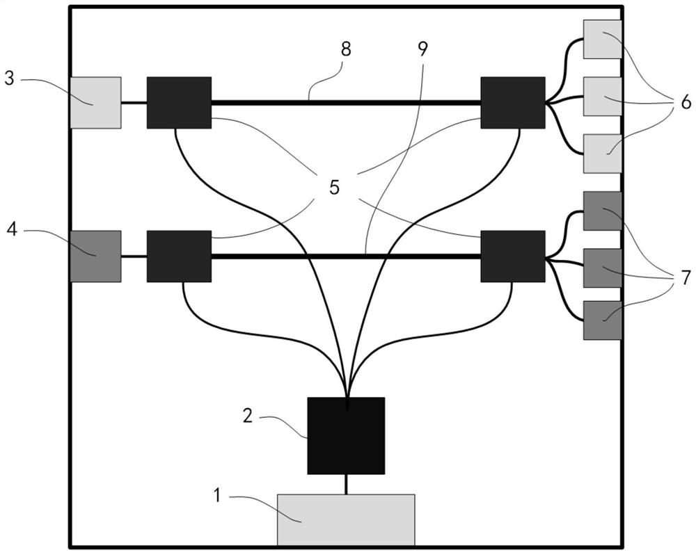
[0039] A system for remotely controlling test power and signals in the embodiment of the present invention is figure 1 As shown, the following embodiments describe the switching process of the electronic system under test once. The corresponding total power supply can be a linear power supply, the upper computer for data interaction can be a data processing computer terminal, and the upper computer responsible for sending control signals can be personal computer.

[0040] Such as Figure 1-Figure 2 As shown, a remote control test power supply and signal system of the present invention includes a control signal interface 1, a microprocessor 2, a power input interface 3, a data signal upper interface 4, a multiple-choice switch 5, and a power output interface 6. Data signal lower interface 7, power supply path 8, data signal path 9. T...


PUM


Abstract

The invention provides a system for remotely controlling a test power supply and signals and a control method. The system comprises a control signal interface for receiving a control signal transmitted from an upper computer, a microprocessor which is used for decoding the received control signal and converting the control signal into a control signal, a power input interface which is connected with a main power supply, a data signal upper interface which is used for bearing a data signal of a test, a one-out-of-multiple switch which is used for controlling the connection direction so as to connect a power path or the data path with specific test electronic equipment, the power path which is used for bearing electric energy for driving the test electronic equipment, the data signal path which is used for bearing a data signal, a power output interface which is used for being connected with a power supply interface of the test electronic equipment, and a data signal lower interface which is used for being connected with a data interface of the test electronic equipment. The control method is implemented based on the system. The system has the advantages that the power and signal paths can be effectively controlled in a remote control mode, the test efficiency is improved, and the safety is ensured.

Description

Technical field [0001] The present invention mainly relates to the technical field of electronic testing, and particularly refers to a system and control method for remotely controlling test power and signals. Background technique [0002] As the application environment of electronic systems becomes more and more complex, the reliability test environment for various electronic products has become more diverse. Electronic products are often used in extreme environmental fields such as medical treatment, aerospace, and nuclear industry, which face extreme environmental conditions such as high temperature, high cold, high pressure, vacuum, high humidity, high-energy particle radiation, complex chemistry, and complex electromagnetics. Many of these environments are not pleasant to enter, and some environmental conditions are even fatal, or the biological itself or the required physical and chemical characteristics and environment will break the test environment. For example: Accordi...

Claims


Application Information

Patent Timeline
Patent Type & Authority Applications(China)
IPC IPC(8): G01R1/28
CPCG01R1/28
Inventor 孙乾池雅庆梁斌陈建军郭阳袁珩洲刘必慰宋睿强吴振宇
Owner NAT UNIV OF DEFENSE TECH
Why Eureka
Try Eureka