Flue gas waste heat cooling and recycling device

A cooling recovery device and flue gas waste heat technology, applied in the field of flue gas waste heat recovery, can solve the problems of low thermal energy utilization effect, external air pollution, poor flue gas purification and cooling effect, etc. The effect of increasing the contact area

Inactive Publication Date: 2020-09-08
李峻岭
View PDF1 Cites 0 Cited by
  • Summary
  • Abstract
  • Description
  • Claims
  • Application Information

AI Technical Summary

Problems solved by technology

[0005] In order to solve the above technical problems, the present invention provides a flue gas waste heat cooling and recovery device to solve the problem that the existing similar flue gas waste heat cooling and recovery devices have a low utilization effect on the heat energy contained in the flue gas when the flue gas circulates. The speed is fast, and the heat contained in the flue gas is difficult to fully conduct to the water flow circulating in the device, which makes it difficult to make full use of most of the heat contained in the flue gas, which affects the utilization effect of the internal heat energy of the flue gas, and affects the device. The flue gas discharged from the interior has a poor purification and cooling effect, and the harmful particles contained in the flue gas are likely to pollute the outside air and affect the surrounding air quality.

Method used


Image

  • Flue gas waste heat cooling and recycling device
  • Flue gas waste heat cooling and recycling device
  • Flue gas waste heat cooling and recycling device

Examples


Embodiment

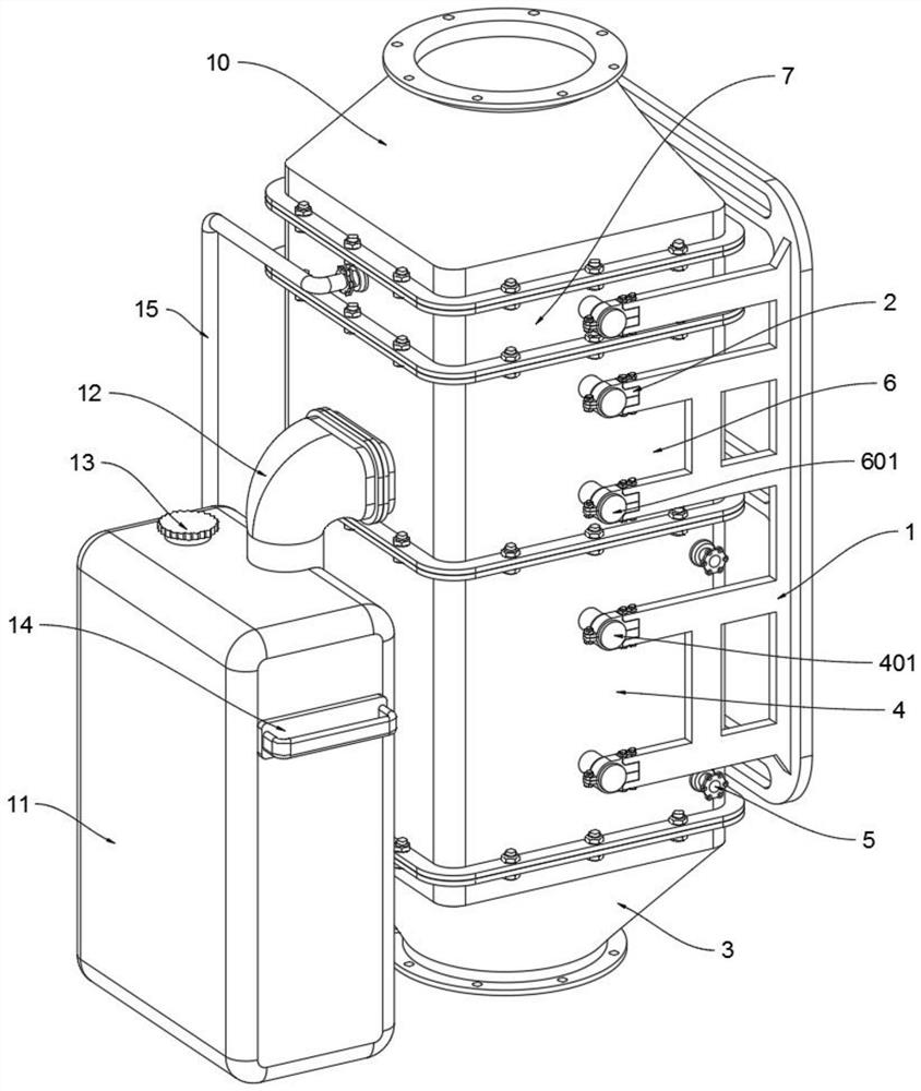
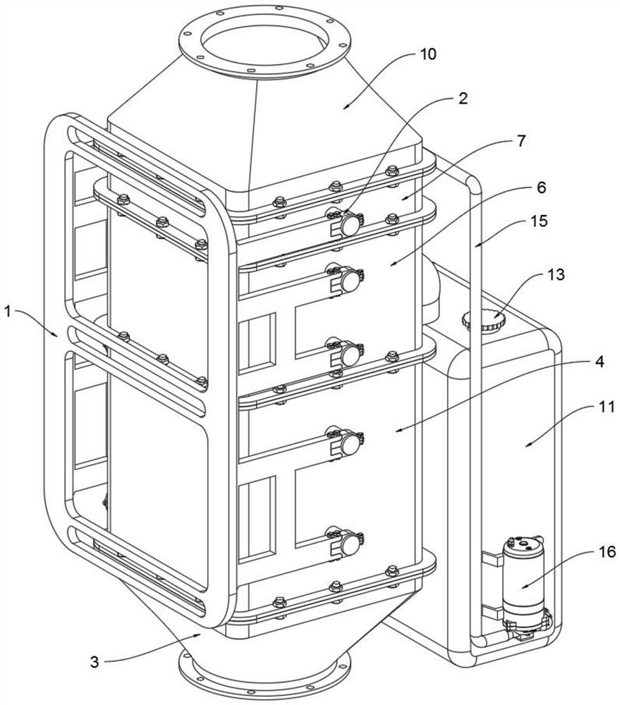
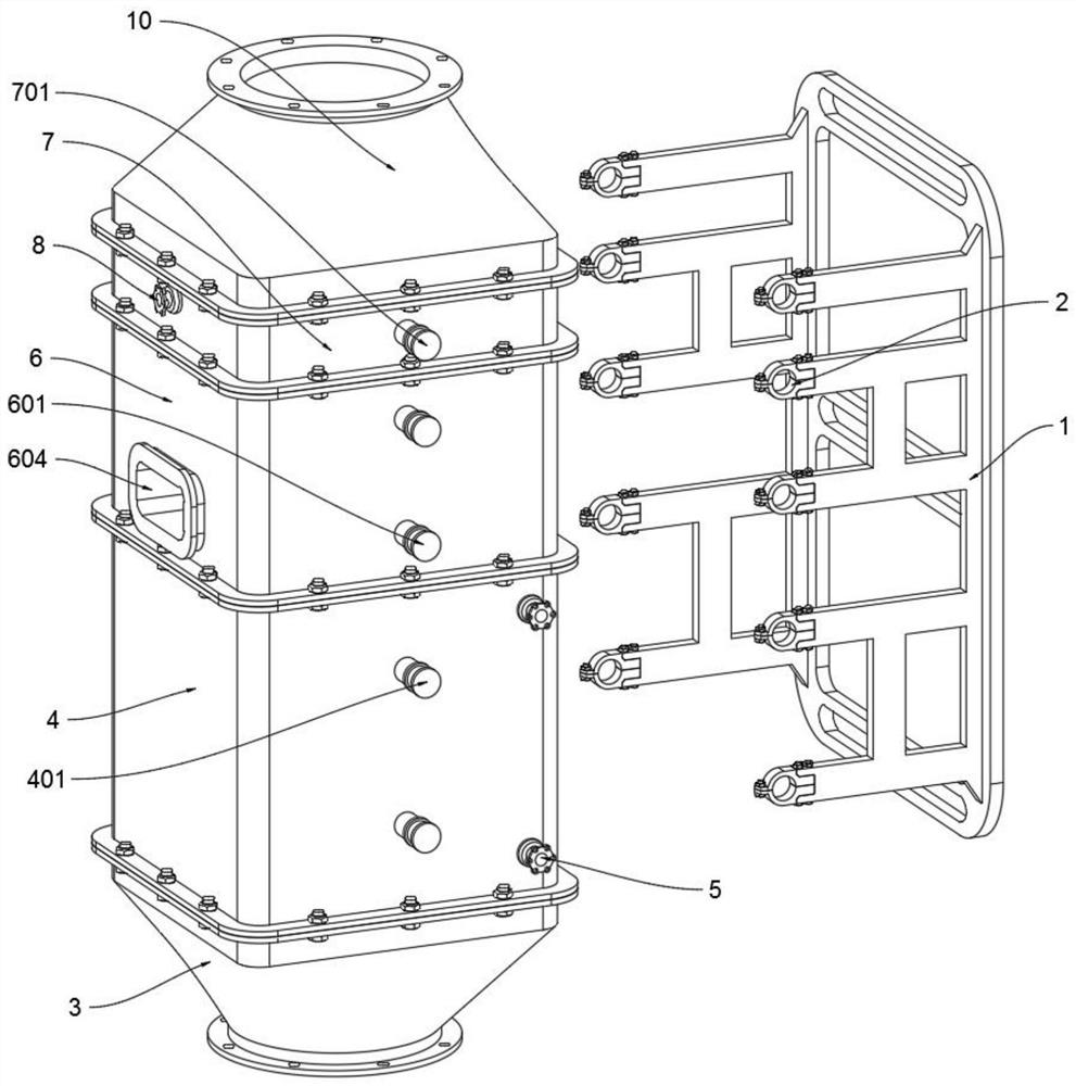
[0035] as attached figure 1 to attach Figure 11 Shown:

[0036]The invention provides a flue gas waste heat cooling recovery device, which includes a movable support frame 1, a smoke inlet pipe body 3, a middle pipe body 6, a water storage tank 11 and a pump body 16; the rear end of the movable support frame 1 is installed on the supporting wall through bolts above, and the connector 2 is symmetrically connected to both sides of the front end of the movable support frame 1; the bottom of the smoke inlet pipe body 3 is connected to the flue gas pipe through bolts, and the top of the smoke inlet pipe body 3 is connected to the bottom of the bottom pipe body 4; The bottom of the tube body 6 is connected to the top of the bottom tube body 4, and the top of the middle tube body 6 is connected to the bottom of the upper tube body 7 through bolts, and the connecting columns B601 on the left and right sides of the middle tube body 6 are respectively connected to the front connector ...


PUM


Abstract

The invention provides a flue gas waste heat cooling and recycling device. The flue gas waste heat cooling and recycling device comprises a bottom pipe body and a waste heat recycling pipe, wherein the rear end of a movable supporting frame is installed on a supporting wall through bolts, and connecting pieces are symmetrically connected to the two sides of the front end of the movable supportingframe; the bottom of a flue gas inlet pipe body is connected with a flue gas pipeline through bolts, and the top of the flue gas inlet pipe body communicates with the bottom of the bottom pipe body; and the bottom of a middle pipe body communicates with the top of the bottom pipe body, and the top of the middle pipe body is connected with the bottom of an upper pipe body through bolts. According to the flue gas waste heat cooling and recycling device, a heat conduction plate on the outer side of the waste heat recycling pipe makes contact with flue gas, the contact area between the waste heatrecycling pipe and the flue gas is increased, heat contained in the flue gas is better conducted into water flow in the waste heat recycling pipe, and the water flow temperature rising efficiency is improved; and the rising flue gas is blocked through a flue gas blocking strip, the flue gas circulation speed is decreased, the heat contained in the flue gas is fully conducted into the water flow inthe waste heat recycling pipe, and the water flow temperature rising efficiency is further improved.

Description

technical field [0001] The invention belongs to the technical field of flue gas waste heat recovery, and more specifically relates to a flue gas waste heat cooling recovery device. Background technique [0002] In the operation of gas-fired boilers, the loss of flue gas waste heat resources is the most important loss of waste heat resources, accounting for 60% to 70% of the loss of boiler waste heat resources. The exhaust gas temperature is the main factor affecting the loss of flue gas waste heat resources. At present, the actual exhaust gas temperature of enterprises using boilers in my country is generally higher than the design temperature. Generally, every 10°C reduction in exhaust gas temperature reduces the loss of flue gas waste heat resources by 0.6%. ~1%, the corresponding saving of energy consumption is 1.2%~2.4%, and the economic benefit is remarkable. Therefore, in the context of the current implementation of energy-saving and emission-reduction policies, it is ...

Claims


Application Information

Patent Timeline
Patent Type & Authority Applications(China)
IPC IPC(8): F28D7/08F28F1/24F28C3/06F23J15/04F23J15/06B01D47/06B01D35/027B01D29/01B01D29/96
CPCB01D29/01B01D29/96B01D35/027B01D47/06B01D2247/04F23J15/04F23J15/06F28C3/06F28D7/082F28F1/24Y02B30/52Y02E20/30Y02P70/10
Inventor 李峻岭
Owner 李峻岭
Why Eureka
Try Eureka