Residual stress peak position positioning method based on acoustic emission technology

An acoustic emission technology and residual stress technology, applied in the field of non-destructive testing, to achieve the effect of good acquisition

Active Publication Date: 2020-09-11
SHANGHAI MARITIME UNIVERSITY
View PDF3 Cites 0 Cited by
  • Summary
  • Abstract
  • Description
  • Claims
  • Application Information

AI Technical Summary

Problems solved by technology

[0005] In order to solve the problem that there is no better positioning method for the residual stress peak position to determine the residual stress peak position in the workpiece, th

Method used


Image

  • Residual stress peak position positioning method based on acoustic emission technology
  • Residual stress peak position positioning method based on acoustic emission technology
  • Residual stress peak position positioning method based on acoustic emission technology

Examples


Embodiment Construction

[0073] With reference to accompanying drawing, further illustrate the present invention:

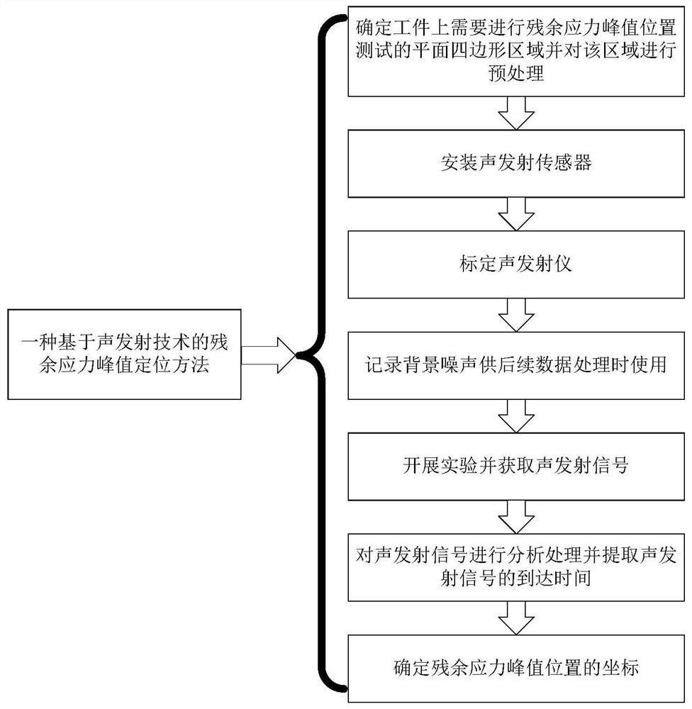
[0074] The location method of residual stress peak position based on acoustic emission technology includes the following steps:

[0075] (1) Determine the planar quadrilateral area on the workpiece that needs to be tested for the peak position of residual stress: firstly, simulate the machining process of the workpiece through finite element numerical simulation technology, obtain the distribution state of the surface residual stress of the workpiece, and obtain the area where the larger residual stress is located , and preliminarily obtain the peak position of the residual stress; secondly, determine a plane quadrilateral area including the preliminarily obtained peak position of the residual stress, which is the test area; then polish the surface of the test area to reduce the surface roughness of the workpiece and ensure that the acoustic emission The sensor can be closely attached to...


PUM


Abstract

The invention discloses a residual stress peak position positioning method based on an acoustic emission technology. The method comprises the following steps of determining a planar quadrilateral region needing residual stress peak position test on a workpiece,mounting an acoustic emission sensor,calibrating an acoustic emission instrument,recording background noise,carrying out an experiment,analyzing and processing the acoustic emission signal, and extracting the arrival time of the acoustic emission signal, and determiningcoordinates of a residual stress peak position. The method has the advantages that the residual stress peak value position can be quickly positioned, and the positioning precision is high.

Description

technical field [0001] The invention relates to the technical field of nondestructive testing, in particular to a residual stress peak position positioning method based on acoustic emission technology. Background technique [0002] During the manufacturing process, the workpiece is affected and affected by various technological factors such as welding, casting, heat treatment, cutting, forging, etc. At the same time, there will also be forced assembly due to incongruous dimensions during the assembly process, which will be in the workpiece Unnecessary residual stress is generated inside, thereby reducing the static load strength and fatigue strength of the workpiece and accelerating the stress corrosion process of the workpiece. It is also an important factor affecting the deformation and cracking of the workpiece. In addition, fatigue cracks are easily formed at the peak value of residual stress, which will lead to the failure of the entire workpiece and affect the service ...

Claims


Application Information

Patent Timeline
IPC IPC(8): G01N29/14G01L5/00G01N29/44G01S5/22
CPCG01N29/14G01L5/0047G01N29/44G01S5/22G01N2291/011G01N2291/023G01N2291/0234G01N2291/02827Y02P10/20
Inventor 顾邦平王中山霍志鹏胡雄王萍
Owner SHANGHAI MARITIME UNIVERSITY
Why Eureka
Try Eureka