Self-irrigation system for sponge city roof garden

A sponge city and roof technology, applied in applications, gardening, watering devices, etc., can solve the problems of plant dehydration, high energy consumption, time-consuming and labor-intensive problems, and achieve good watering effects, save energy, and increase collection.

Active Publication Date: 2020-09-15
苏州市绿野景观园林工程有限公司
View PDF8 Cites 4 Cited by
  • Summary
  • Abstract
  • Description
  • Claims
  • Application Information

AI Technical Summary

Problems solved by technology

[0003] At present, the roof garden has the function of collecting and utilizing rainwater, but when watering the plants on the roof garden, people need to pump the collected rainwater through the water pump, so as to sprinkle it on the plants, and the rainwater is extracted through the water pump. It consumes a lot of power and is noisy, which is not conducive to the...

Method used


Image

  • Self-irrigation system for sponge city roof garden
  • Self-irrigation system for sponge city roof garden
  • Self-irrigation system for sponge city roof garden

Examples


Embodiment 1

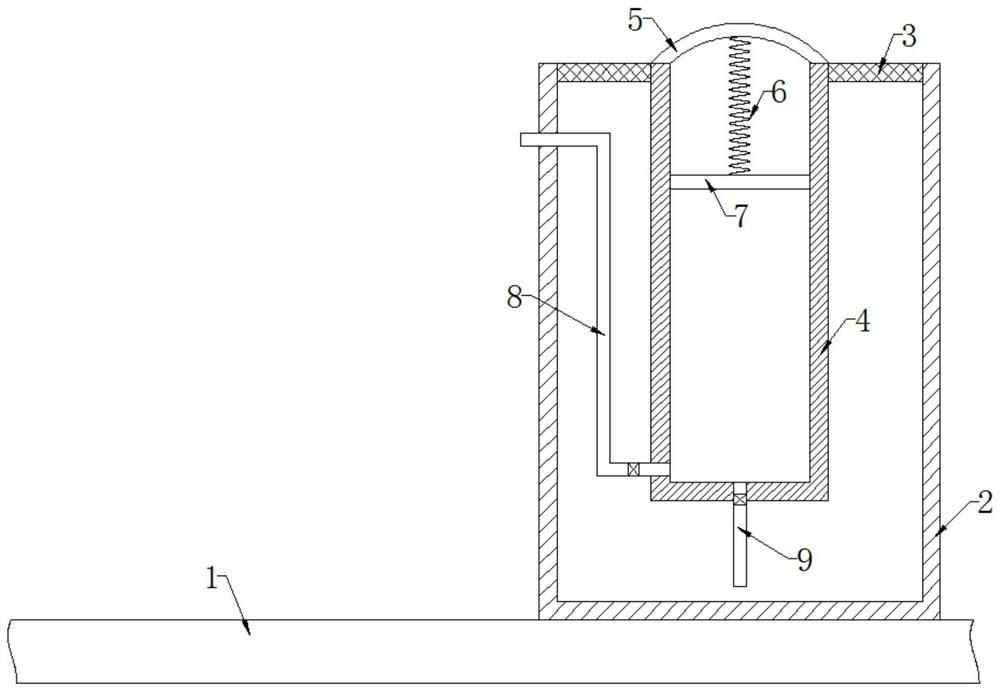
[0021] refer to figure 1 , a self-watering system for roof gardens in sponge cities, including a water collection tank 2 fixedly connected to the upper end of the roof 1, and an annular filter plate 3 fixedly connected to the upper end of the water collection tank 2, which can prevent external impurities from entering the water collection tank 2, causing the water collection tank to 2 The water quality is poor, which may easily lead to blockage of the outlet pipe. The side wall of the annular filter plate 3 is fixedly connected with a sliding plug cylinder 4, and the upper end of the sliding plug cylinder 4 is fixedly connected with an arc-shaped hard plate 5. The hard plate 5 is made of transparent material. The inner wall of the sliding plug cylinder 4 is sealed and slidably connected with a sliding plug 7, and the upper part of the sliding plug cylinder 4 is located at the sliding plug 7 and filled with evaporating liquid. Further, the side wall of the hard plate 5 is fixedl...

Embodiment 2

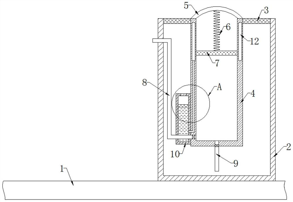
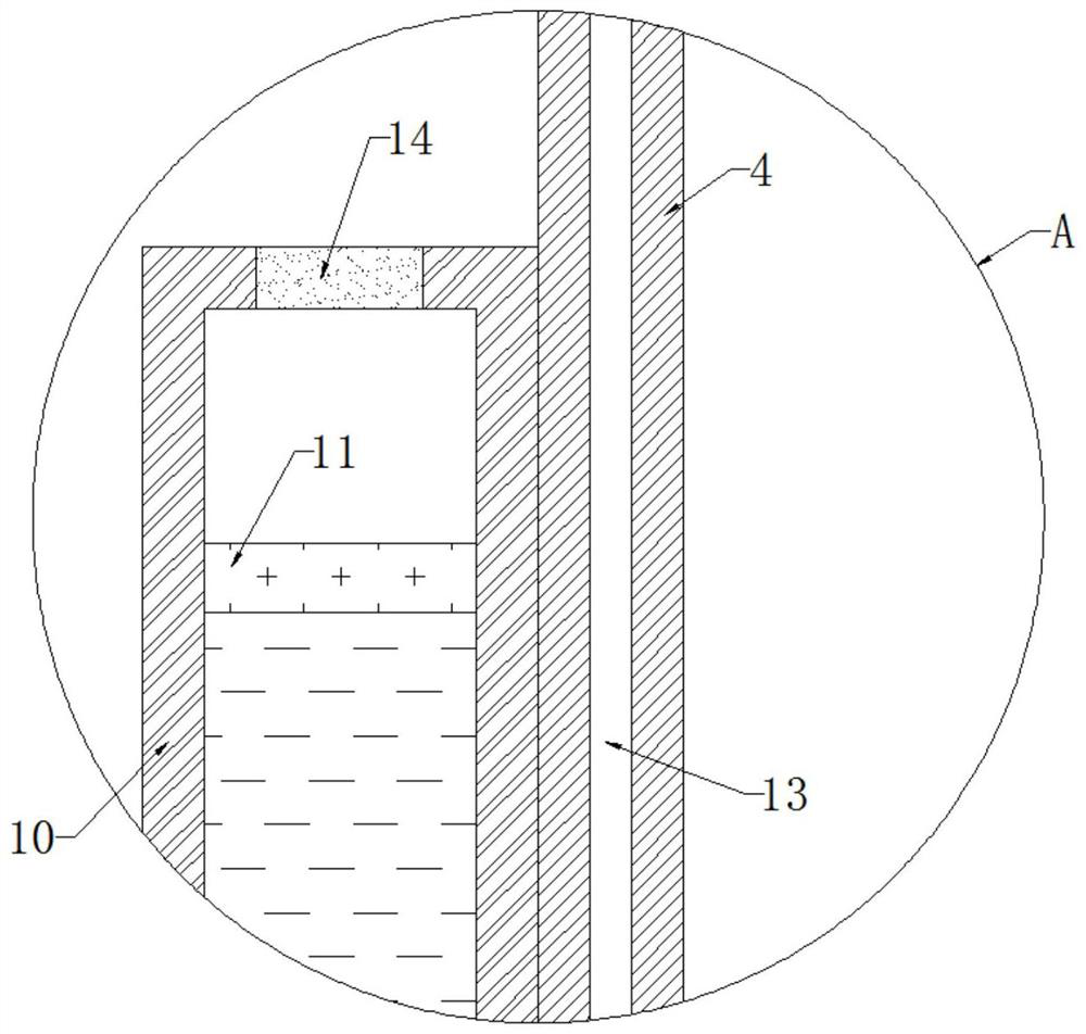
[0024] refer to Figure 2-3 The difference from the first embodiment is that the sliding plug 7 is made of magnetic material, the side wall of the sliding plug barrel 4 is fixedly connected with a cooling box 10, and the cooling box 10 is made of thermal insulation material, and the inner wall of the cooling box 10 is sealed and slidingly connected with a The magnetic slide plate 11 made of lightweight material, the cooling box 10 is located at the bottom of the magnetic slide plate 11 and filled with cooling liquid, the cooling liquid can be liquid nitrogen, further, the magnetic slide plate 11 made of light material can be placed on the cooling liquid The buoyancy is relatively large, so that the cooling liquid can flow inside and outside the cooling box 10 relatively easily. The cooling box 10 made of thermal insulation material can prevent the cooling liquid in the cooling box 10 from cooling the water in the water collection tank 2, so that the inside of the cooling liquid...


PUM


Abstract

The invention discloses a self-irrigation system for a sponge city roof garden. The system comprises a water collecting tank fixedly connected to the upper end of a roof; an annular filter plate is fixedly connected to the upper end of the water collecting tank; a sliding plug cylinder is fixedly connected to the side wall of the annular filter plate; an arc-shaped hard plate is fixedly connectedto the upper end of the sliding plug cylinder; the hard plate is made of transparent materials; a sliding plug is connected to the inner wall of the sliding plug cylinder in a sealed and sliding mode;the upper portion, located on the sliding plug, of the sliding plug cylinder is filled with evaporation liquid; and the lower end of the hard plate is fixedly connected with the upper end of the sliding plug through a reset spring. When external sunlight irradiates intensely, the sunlight penetrates through the hard plate, so that the temperature in the evaporation liquid is gradually increased,evaporation of the evaporation liquid pushes the sliding plug to slide downwards, water in the sliding plug cylinder is extruded out through a one-way water outlet pipe, and automatic irrigation of plants is achieved; and meanwhile, external electric energy supply is not needed, so that energy is effectively saved.

Description

technical field [0001] The invention relates to the technical field of sponge cities, in particular to a self-watering system for roof gardens in sponge cities. Background technique [0002] Sponge city is a new generation of urban stormwater management concept. In the construction of sponge city, roof gardens can not only increase the urban green area, reduce the urban heat island effect, but also beautify the city, purify the air, and effectively improve people's living environment and improve the quality of life. [0003] At present, the roof garden is equipped with the function of collecting and utilizing rainwater, but when watering the plants on the roof garden, people need to pump the collected rainwater through the water pump, so as to sprinkle it on the plants, and the rainwater is extracted through the water pump. It consumes a lot of power and is noisy, which is not conducive to the construction of the sponge city. In addition, when watering the plants, the water...

Claims


Application Information

Patent Timeline
IPC IPC(8): A01G25/02A01G25/16E03B3/02E03B11/00
CPCA01G25/02A01G25/16A01G25/165E03B3/02E03B11/00Y02A20/108
Inventor 陈静郭雪虎
Owner 苏州市绿野景观园林工程有限公司
Why Eureka
Try Eureka