Industrial waste liquid neutralizing device

A technology of industrial waste liquid and tank, which is applied in the field of industrial waste liquid neutralization devices, can solve problems such as insufficient agitation, influence of neutralization reaction, pollution of the environment and staff, and achieve the effect of improving the working environment and work efficiency

Inactive Publication Date: 2020-09-15
杭州迦北科技有限公司
View PDF4 Cites 0 Cited by
  • Summary
  • Abstract
  • Description
  • Claims
  • Application Information

AI Technical Summary

Problems solved by technology

[0004] The purpose of the present invention is to provide a kind of industrial waste liquid neutralization device, to solve the problem that present industrial waste water needs to be neutralized and reprocessed when it is processed in the above-mentioned background technology, the present neutralization device is simple The box is used to hold materials, and then the cover needs to be opened to add additives for neutralization. Since the smell of waste water is also polluting, the environment and staff will be polluted when the cover is opened, making it impossible to carry out high Efficiently complete the neutralization task, and it needs to be agitated to fully neutralize the neutralization. The traditional agitation is a simple single-channel agitation rod for the internal agitation of the box, resulting in insufficient agitation and insufficient mixing. At the same time, during long-term neutralization, there will be precipitation on the bottom of the box, and it cannot be stirred by simple stirring, which leads to the problem that the neutralization reaction inside the box is affected to a certain extent.

Method used


Image

  • Industrial waste liquid neutralizing device
  • Industrial waste liquid neutralizing device
  • Industrial waste liquid neutralizing device

Examples


Embodiment Construction

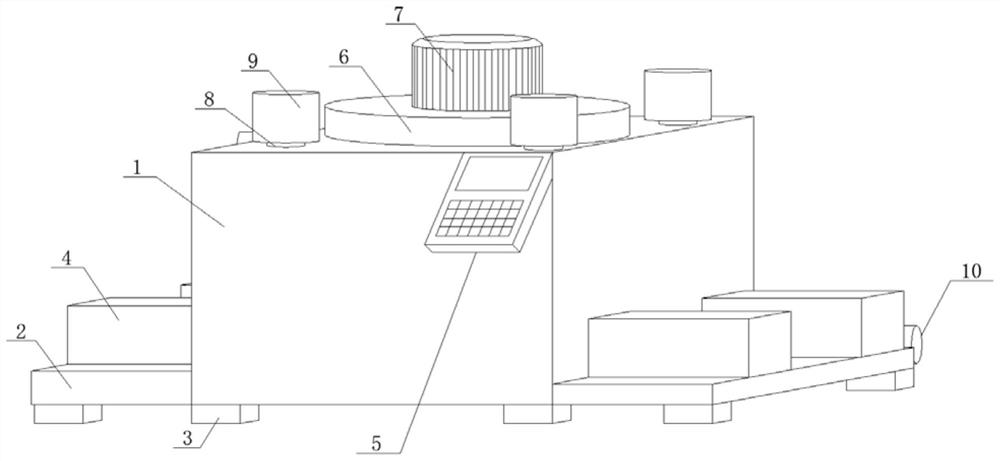
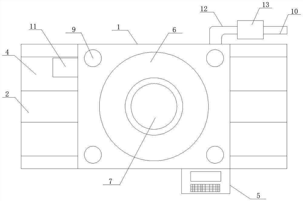
[0028] see Figure 1-2 , in an embodiment of the present invention, an industrial waste liquid neutralization device includes a neutralization box 1, the two sides of the neutralization box 1 are horizontally welded with a support pallet 2, and the neutralization box 1 and the support pallet 2 The bottom surface of the base is fixedly welded with support pads 3, and the number of support plates 2 is two, and the two support plates 2 are arranged horizontally and symmetrically on both sides of the neutralization box 1 near the bottom surface, and the two support plates The bottom surface of the plate 2 and the bottom surface of the neutralization box 1 are kept at the same horizontal plane position, the thickness of the two support pallets 2 is not the same, the number of the support pads 3 is several, and the multiple support pads 3 are respectively Fixedly installed on the bottom surface of the neutralization box 1 and the support pallet 2 near the edge, the top surface of th...


PUM


Abstract

The invention discloses an industrial waste liquid neutralizing device, and relates to the field of industrial waste liquids. The industrial waste liquid neutralizing device comprises a neutralizing box body, supporting plates are horizontally welded to the two side edges of the neutralizing box body. Supporting cushion blocks are fixedly welded on the bottom surfaces of the neutralizing box bodyand the supporting plate; the top face of the supporting plate is horizontally connected with a pushing air cylinder through bolts. A control panel is obliquely welded to one side edge of the neutralizing box body, a top disc is horizontally welded to the top face of the neutralizing box body, a stirring motor is vertically connected to the top face of the top disc through bolts, butt joint screwholes are evenly formed in the top face of the neutralizing box body, and additive bottles are connected to the inner side edges of the butt joint screw holes through bolts. The device is simple in design structure and convenient to operate, neutralization is more sufficient under the action of multiple stirring, meanwhile, cleanness and sanitation are achieved in a non-contact additive feeding mode, and the working environment and the working efficiency are greatly improved.

Description

technical field [0001] The invention relates to the technical field of industrial waste liquid treatment, in particular to an industrial waste liquid neutralization device. Background technique [0002] Industrial wastewater includes production wastewater, production sewage and cooling water. It refers to wastewater and waste liquid produced in the process of industrial production, which contains industrial production materials, intermediate products, by-products and pollutants produced in the production process lost with water. There are many types of industrial wastewater with complex components. For example, electrolytic salt industrial wastewater contains mercury, heavy metal smelting industrial wastewater contains various metals such as lead and cadmium, electroplating industrial wastewater contains various heavy metals such as cyanide and chromium, petroleum refining industrial wastewater contains phenol, and pesticide manufacturing industrial wastewater contains Cont...

Claims


Application Information

Patent Timeline
IPC IPC(8): C02F1/66
CPCC02F1/66
Inventor 陈婷婷
Owner 杭州迦北科技有限公司
Why Eureka
Try Eureka