Compensation transformer and energy storage module combined current-voltage compensation system

A technology for compensating transformers and energy storage modules, applied in AC network voltage adjustment, reactive power compensation, reactive power adjustment/elimination/compensation, etc. Parallel reactive power compensation equipment improves terminal voltage characteristics and other issues, and achieves the effect of providing space-time power and energy regulation capabilities, reducing power supply and grid construction, and delaying power supply and grid construction.

Active Publication Date: 2020-09-15
SHANGHAI UNIV
View PDF8 Cites 1 Cited by
  • Summary
  • Abstract
  • Description
  • Claims
  • Application Information

AI Technical Summary

Problems solved by technology

Due to the large power supply radius, it is easy to have low power supply voltage at the end of the line and unqualified power quality. With the continuous increase of user load, the single-point large load continues to increase, and the peak and valley fluctuations of the power grid day and night, located at the end of the line The user's power supply quality will be more affected. In addition, in the western region where the load is dispersed, wind energy and light energy are sufficient, and there are wind power stations and photovoltaic power stations along the transmission line. The intermittent, random, and Volatility also poses a great challenge to the safe and economical operation of the power grid, and blindly increasing power generation to ensure power supply for users will cause a lot of waste of power resources, which violates the concept of smart grid construction and operation. Without mandatory demand-side management, improving resource reuse rate, utilizing the peak-valley characteristics of the power grid, and solving the problem of power grid peak-valley load regulation have gradually attracted the attention of the society.
[0003] In the existing technology, the load is scattered, and the power supply radius of the substation and distribution station is limited. Longer medium-voltage lines and scattered substations and distribution stations are often required to realize the power supply of the entire area, and the utilization rate of the main transformer of the scattered substation is low. Most of the power loss is in the process of line transmission, and it is mainly due to the loss caused by the active current flowing through the long transmission line. It is impossible to improve the terminal voltage characteristics by simply connecting reactive power compensation equipment in parallel. In addition, based on the principle of autotransformer The compensation device used to raise the voltage will also fail when the load is heavy, or even worsen. The reason is that the line cannot transmit such a large capacity when the load is heavy. Voltage compensation must be implemented based on the principle of active compensation
However, some existing active compensation equipment requires the grid to provide additional compensation current by taking power from the grid as its energy source, and this current flowing through the transmission line will cause a large amount of additional line loss, and when the load When it exceeds a certain range, the current consumed by the compensation will also increase, which will cause the compensation to fail

Method used


Image

  • Compensation transformer and energy storage module combined current-voltage compensation system
  • Compensation transformer and energy storage module combined current-voltage compensation system
  • Compensation transformer and energy storage module combined current-voltage compensation system

Examples


Embodiment Construction

[0035] The following will clearly and completely describe the technical solutions in the embodiments of the present invention with reference to the accompanying drawings in the embodiments of the present invention. Obviously, the described embodiments are only some, not all, embodiments of the present invention. Based on the embodiments of the present invention, all other embodiments obtained by persons of ordinary skill in the art without making creative efforts belong to the protection scope of the present invention.

[0036] In order to make the above objects, features and advantages of the present invention more comprehensible, the present invention will be further described in detail below in conjunction with the accompanying drawings and specific embodiments.

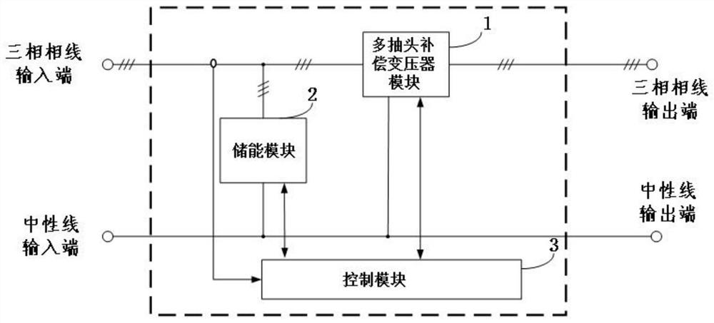
[0037] like figure 1As shown, a current-voltage compensation system combining a compensation transformer and an energy storage module is characterized in that it includes: a multi-tap compensation transformer modu...


PUM


Abstract

The invention discloses a current-voltage compensation system combining a compensation transformer and an energy storage module, and the system comprises a multi-tap compensation transformer module which is used for taking power from a power grid and then compensating the voltage of a power supply line so as to enable the voltage of the tail end of the line to meet the standard; an energy storagemodule which is connected with a three-phase line and a neutral line of a power supply line and is used for realizing peak-valley load adjustment; and a control module which is connected with the multi-tap compensation transformer module and the energy storage module and is used for detecting voltage and current information of the power supply line, generating a control instruction and controllingthe multi-tap compensation transformer module and the energy storage module according to the control instruction. The independent adjustment of the three-phase voltage can be realized, the adjustmentis bidirectional, the compensation transformer can be supported to work normally at the peak of power utilization through the peak regulation effect of the energy storage module, and the applicability is higher.

Description

technical field [0001] The invention relates to the field of power supply or power distribution, in particular to a current-voltage compensation system combining a compensation transformer and an energy storage module. Background technique [0002] Under the background that the State Grid is fully committed to promoting the construction of "Strong Smart Grid, Ubiquitous Power Internet of Things" and building a "hub-type, platform-type, and shared" energy Internet, inland high-altitude areas, due to the high altitude of the region, the climate The conditions are harsh, and the construction and maintenance process of the power grid is extremely difficult, but the investment and operation and maintenance costs are much higher than those in the developed eastern regions. How to provide suitable power supply services to the population in areas with scattered loads in a more economical way has become a worldwide hot topic. Due to the large power supply radius, it is easy to have ...

Claims


Application Information

Patent Timeline
Patent Type & Authority Applications(China)
IPC IPC(8): H02J3/12H02J3/32H02J3/18
CPCH02J3/12H02J3/1807H02J3/32Y02E40/30
Inventor 徐国卿乔畅
Owner SHANGHAI UNIV
Why Eureka
Try Eureka