
Inspection device

A technology for inspection devices and inspection objects, which is applied in the direction of measuring devices, instruments, fluid resistance measurement, etc., and can solve problems such as packaging, transportation methods, and detection difficulties that cannot be applied

Active Publication Date: 2020-09-15
CANON DENSHI KK
View PDF25 Cites 0 Cited by
  • Summary
  • Abstract
  • Description
  • Claims
  • Application Information

AI Technical Summary

Problems solved by technology

[0003] In the past, there were inspection methods such as optical inspection and X-ray fluoroscopy, but there were packaging and transportation methods that could not be applied to these methods, so a method of detecting foreign objects based on other principles was sought
[0004] As one of the foreign object detection methods, there is a method of detecting the residual magnetism of the magnetic foreign object moving in the conveyance path with a magnetic sensor, but when the size of the magnetic foreign object is small, the value of the residual magnetism becomes extremely small, so the detection become difficult, it is well known

Method used


Image

  • Inspection device
  • Inspection device
  • Inspection device

Examples


no. 1 approach

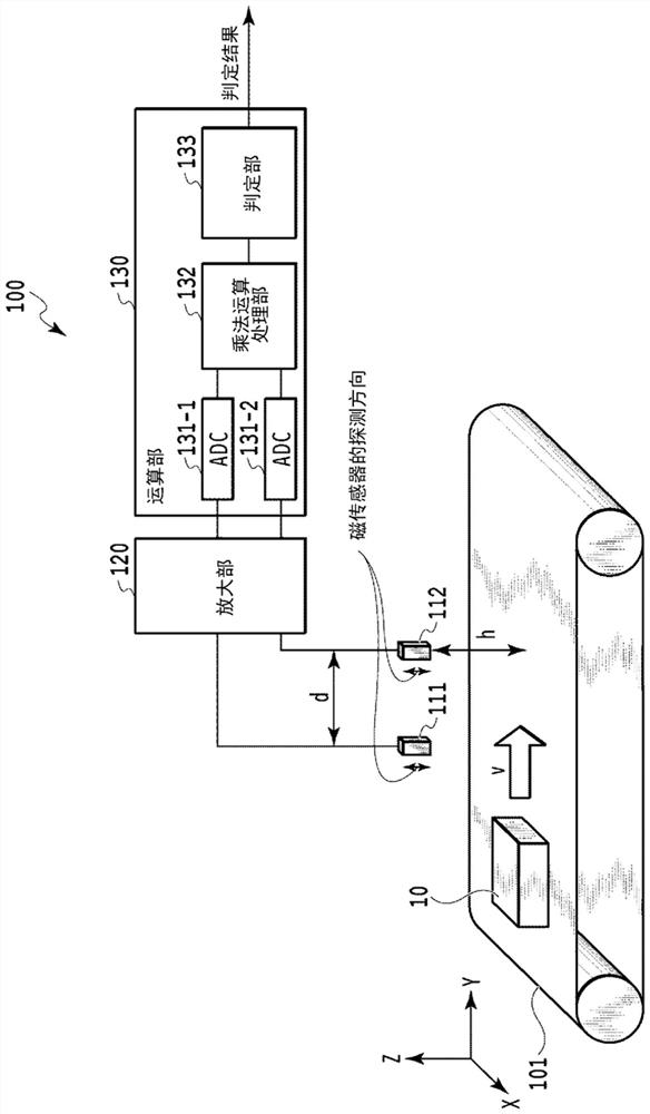
[0055] exist figure 1 In , the configuration of the inspection device according to the first embodiment of the present invention is shown. The inspection apparatus 100 is provided with: a conveyance path 101, which conveys the object 10 to be inspected at a moving speed v; Detection; Amplifying section 120, which amplifies the detection signal of the first magnetic detector 111 and the detection signal of the second magnetic detector 112 respectively; The signal obtained by the delay is multiplied by the detection signal of the second magnetic detector 112 .

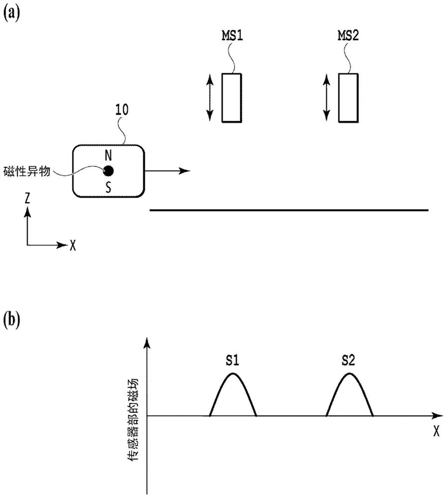
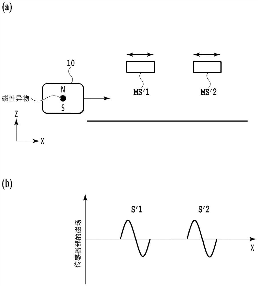
[0056] exist figure 1 In the shown configuration, for the sake of simplicity of description, each of the first magnetic detector 111 and the second magnetic detector 112 has one magnetic sensor, and these two sensors are a pair of sensors. A magnetic sensor MS1 as the first magnetic detector 111 having a magnetic field detection direction perpendicular to the conveying surface is disposed at a height h from the conv...

no. 2 approach

[0087] exist Figure 9 In , the configuration of the inspection device according to the second embodiment of the present invention is shown. In the second embodiment, a configuration is shown in which the detection accuracy of detecting magnetic foreign objects in the width direction of the conveyance path 101 and in the vertical direction of the conveyance path 101 is improved. The inspection apparatus 200 is provided with: a conveyance path 101, which conveys the object 10 to be inspected at a moving speed v; Detection; Amplifying section 220, which amplifies the detection signal of the first magnetic detector 211 and the detection signal of the second magnetic detector 212 respectively; The signal obtained by the delay is multiplied by the detection signal of the second magnetic detector 212 .

[0088] In the first embodiment, the structure in which the first magnetic detector 111 and the second magnetic sensor 112 each have one magnetic sensor was described as an example...

no. 3 approach

[0095] 3rd Embodiment describes the structure of the inspection apparatus which makes the detection accuracy of the magnetic foreign object of 1st Embodiment and 2nd Embodiment more accurate. Note that descriptions of items common to the first embodiment and the second embodiment are omitted.

[0096] In the third embodiment, the arithmetic processing units 130 , 230 of the inspection devices 100 , 200 further include means for averaging detection signals and periodic noise removal means. These means can be used to perform averaging processing on the detection signals of the first magnetic detectors 111, 211 and the second magnetic detectors 112, 212, respectively. The averaging processing may also be moving average, summed average, or the like. By performing averaging processing, noise can be rounded, and the S / N ratio of multiplication processing can be improved. In addition, averaging processing may be performed on the multiplication results.

[0097] The transport path ...


PUM


Abstract

The purpose of the present invention is to provide an inspection device which, irrespective of the passing position of an inspection target, does not have a dead zone, does not have a change in polarity of a detection signal waveform, and can consecutively perform inspection. The inspection device (100) is provided with: a transport path (101) in which the inspection target is transported at a moving velocity v; a first magnetic detector (111) and a second magnetic detector (112) which detect the magnetism of magnetic foreign matter included in the inspection target (10); an amplifying unit (120) which amplifies each of detection signals from the first magnetic detector (111) and the second magnetic detector (112); and a calculation processing unit (130) which multiplies a signal, obtainedby delaying the detection signal from the first magnetic detector (111), by the detection signal from the second magnetic detector (112). The first magnetic detector (111) and the second magnetic detector (112) respectively have magnetic sensors which are paired. One magnetic sensor MS1 of the first magnetic detector, which has a vertical magnetic field detection direction, is disposed at a height h from the transport surface, and one magnetic sensor MS2 of the second magnetic detector is disposed at a distance d from the magnetic sensor MS1.

Description

technical field [0001] The present invention relates to an inspection device for detecting foreign matter of a magnetic body contained in an inspection object conveyed on a conveyance path. Background technique [0002] In powder, granular raw materials, molded parts, and various packaged products, there is a risk of foreign matter being mixed in due to falling of fixings such as screws during the manufacturing process, and chipping of blades during the cutting process. When a large amount of objects to be inspected is conveyed continuously, a high-performance sensor is required to remove minute foreign matter mixed in. [0003] Conventionally, there are inspection methods such as optical inspection and X-ray fluoroscopy. However, there are packaging and transportation methods to which these methods cannot be applied. Therefore, a method of detecting foreign objects based on other principles has been sought. [0004] As one of the foreign object detection methods, there is ...

Claims


Application Information

Patent Timeline
Patent Type & Authority Applications(China)
IPC IPC(8): G01V3/11G01V3/10
CPCG01V3/08G01N22/04G01N22/00G01N33/2823G01R27/04G01R25/04G01R27/22G01N27/72G01N27/82G01N27/9046G01N27/9006G01R33/12G01R33/1215
Inventor 松冈贵弘川瀬正博
Owner CANON DENSHI KK
Learn More