
Safety protection device for photovoltaic power station inverter

A safety protection device and photovoltaic power station technology, applied in photovoltaic power generation, photovoltaic modules, output power conversion devices, etc., can solve problems such as easy to bump the inverter, affect the life of the inverter, and increase the temperature of the inverter. To achieve the effect of reducing the spread of high temperature

Inactive Publication Date: 2020-09-18
夏喜明
View PDF15 Cites 2 Cited by
  • Summary
  • Abstract
  • Description
  • Claims
  • Application Information

AI Technical Summary

Problems solved by technology

[0005] In order to solve the above technical problems, the present invention provides a safety protection device for inverters in photovoltaic power stations to solve the problem that when the inverters in the above patents are in use, due to the particularity of the installation position of the photovoltaic panels, the inverter needs a long time Exposure to areas with sufficient sunlight will increase the temperature of the inverter and affect the life of the inverter. During the maintenance and testing of photovoltaic panels, it is easy to bump the inverter. In severe cases, it will damage the inverter and cause photovoltaic power generation. Problems with the device not working properly

Method used


Image

  • Safety protection device for photovoltaic power station inverter
  • Safety protection device for photovoltaic power station inverter
  • Safety protection device for photovoltaic power station inverter

Examples


Embodiment Construction

[0030] Embodiments of the present invention will be further described in detail below in conjunction with the accompanying drawings and examples. The following examples are used to illustrate the present invention, but should not be used to limit the scope of the present invention.

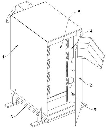
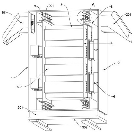
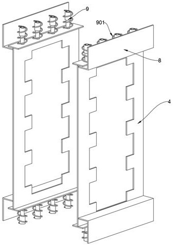
[0031] as attached figure 1 to attach Figure 9 Shown:

[0032] The invention provides a safety protection device for an inverter in a photovoltaic power station, which includes an outer shell 1, a base 3, an inner shell 5, a side shock absorber 6, a folding plate 8, a telescopic rod 9, and a line pipe 10; the outer shell 1 The right side of the right side is hingedly connected to the right side cover 2, and the front side of the right side cover 2 is connected to the right front of the outer shell 1 through a lock; the base 3 is fixedly connected to the top of the outer shell 1; the folding plate is fixedly connected in four places. On the inner upper surface and the lower surface of the outer...


PUM


Abstract

The invention provides a safety protection device for a photovoltaic power station inverter. The safety protection device comprises an outer shell, a base, an inner shell, a side damping seat, a folded plate, a telescopic rod and a wire passing pipe. The right side of the outer shell is hinged to a right side cover, and the front side of the right side cover is connected with the front of the right side of the outer shell through a lock catch; the base is fixedly connected with the upper portion of the outer shell; the four parts of the folded plate are fixedly connected with the upper surfaceand the lower surface of the interior of the outer shell; one end of the telescopic rod is fixedly connected with the upper surface and the lower surface of the interior of the outer shell, and the other end of the telescopic rod is fixedly connected with the two ends of the corresponding side supporting plate; the side support plates are movably connected to the inner sides of the folded plate;the inner shell is slidably connected into the middle openings of the side supporting plates on the two sides; the anti-vibration performance of the inverter protection shell is improved, the probability that the inverter core assembly is damaged by vibration generated in the carrying process is reduced, the effect of limiting the air flow direction can be achieved through an air drainage cover, heat dissipation is more concentrated, and the heat dissipation effect is further improved.

Description

technical field [0001] The invention belongs to the technical field of electric safety protection devices, and more specifically relates to a safety protection device for inverters in photovoltaic power stations. Background technique [0002] Inverters convert DC power into AC power. It consists of inverter bridge, control logic and filter circuit. Widely used in air conditioners, home theaters, electric grinding wheels, electric tools, sewing machines, DVDs, VCDs, computers, TVs, washing machines, range hoods, refrigerators, video recorders, massagers, fans, lighting, etc. In recent years, in order to promote new energy power generation, The construction of photovoltaic power stations is becoming more and more widespread. Since the electric energy generated by photovoltaic panels is direct current, it is not convenient to transmit electric energy. Therefore, installing an inverter can convert the direct current generated by photovoltaic panels into alternating current, whi...

Claims


Application Information

Patent Timeline
IPC IPC(8): H05K5/02H05K5/03H05K5/06H05K7/20H02M7/00H02M1/00H02S40/32F16F15/08
CPCH05K5/0213H05K5/0217H05K5/03H05K7/20909H05K5/0234H05K5/06H02M7/003H02M1/00H02S40/32F16F15/085Y02E10/56
Inventor 夏喜明
Owner 夏喜明
Learn More