
Wood floor double-sided coating method based on 3D printing technology

A 3D printing and technical technology, applied in the direction of special decorative structures, printing post-processing, copying/marking methods, etc., can solve the problems of high wood texture repetition rate, low wood texture fidelity, wood texture type limitations, etc., to achieve overall The effect of strong sense and realistic finishing effect

Active Publication Date: 2020-09-22
湖州市检验检测中心 +1
View PDF7 Cites 0 Cited by
  • Summary
  • Abstract
  • Description
  • Claims
  • Application Information

AI Technical Summary

Problems solved by technology

[0003] (1) Multi-color printing, which uses the existing coating production line to print wood texture on the surface of the profile through an indentation roller and multiple color rollers, but one set of rollers can only print one wood texture, so this method is limited Due to the number of roller plates, the types of wood textures that can be produced are very limited, and the repetition rate of the same wood texture after product paving is high;
[0004] (2) Inkjet printing, which prints the scanned pattern layer (UV pattern layer or ink pattern layer) on the surface of the profile. Although this method can print any wood texture scanned, it is limited by the way of plane printing , so the wood texture lacks three-dimensionality, and the printed wood texture has low fidelity;
[0005] (3) Layer-by-layer inkjet printing, which first prints the scanned pattern layer (UV pattern layer or ink pattern layer) on the surface of the profile, and then sprays transparent or translucent UV or ink on a specific position on the pattern layer to form texture layer, but the texture layer is overlaid on the pattern layer, so the pattern and texture of the wood texture produced by this method are visually separated, and the printed wood texture has low fidelity

Method used


Image

  • Wood floor double-sided coating method based on 3D printing technology
  • Wood floor double-sided coating method based on 3D printing technology
  • Wood floor double-sided coating method based on 3D printing technology

Examples


Embodiment 1

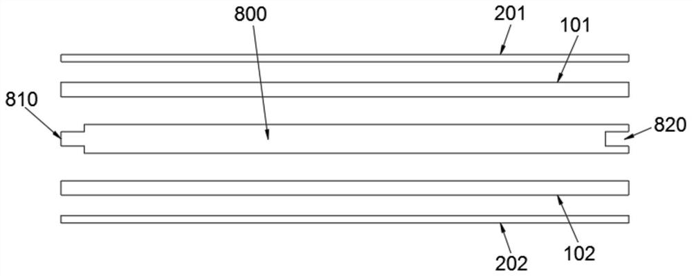
[0050] Example 1: Reference figure 1 As shown, a double-sided coating method for wooden floors based on 3D printing technology includes the following process steps in sequence:

[0051] S1, profile 800 surface and back treatment;

[0052] S2. Scanning a section of the target material with a certain thickness to form color image information and a three-dimensional model;

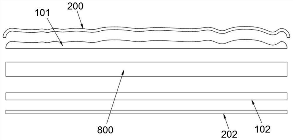
[0053] S3. According to the three-dimensional model, stack printing on the surface and back of the profile 800 to form the upper texture structure layer 101 and the lower texture structure layer 102;

[0054] S4. According to the color image information, UV printing is performed on the upper texture structure layer 101 and the lower texture structure layer 102 respectively to form the upper texture pattern layer 201 and the lower texture pattern layer 202 .

[0055] Through the above method, the upper texture structure layer 101 and the upper texture pattern layer 201 covering it jointly form the 3D coating...

Embodiment 2

[0071] Embodiment 2: The difference between embodiment 2 and embodiment 1 is that in step S3, the original material is used for lamination printing, the original material is wood powder and wear-resistant powder including thermosetting resin with a particle size of 20-50 μm, and is used heat curing to form the upper texture structure layer 101 and the lower texture structure layer 102 .

[0072] In this embodiment, the original material is used for lamination printing, and its raw material is mainly wood powder, which can make the upper texture structure layer 101 and the lower texture structure layer 102 have a more wooden material feeling, and at the same time can effectively improve the texture of the upper texture structure layer 101. 1. The thickness of the lower texture structure layer 102 makes the 3D finishing layer more realistic. In particular, when the thickness of the upper texture structure layer 101 is increased, the treatment process of the 3D coating layer on t...

Embodiment 3

[0075] In this embodiment, the thickness of the upper texture structure layer 101 is 2 mm, and the thickness of each layer is 100 μm, a total of 20 layers, the thickness of the lower texture structure layer 102 is 2 mm, and the thickness of each layer is 100 μm, There are 20 layers in total. In some other embodiments, the thickness of the upper texture structure layer 101, the texture structure layer 100 is 3 mm, the thickness of each layer is 200 μm, and a total of 15 layers, the thickness of the lower texture structure layer 102 is 2 mm, each layer The thickness of the texture structure layer 101 is 100 μm, a total of 20 layers; or, the thickness of the upper texture structure layer 101 is 4 mm, the thickness of each layer is 500 μm, a total of 8 layers, the thickness of the lower texture structure layer 102 is 2 mm, each The thickness of the layers is 100 μm, a total of 20 layers; or the thickness of the upper texture structure layer 101 is 4.8 mm, the thickness of each lay...


PUM

PropertyMeasurementUnit
thicknessaaaaaaaaaa
thicknessaaaaaaaaaa
particle diameteraaaaaaaaaa

Abstract

The invention discloses a wood floor double-sided coating method based on a 3D printing technology. The wood floor double-sided coating method sequentially comprises the following process steps that S1, the surface and the back face of a profile are treated; S2, a target material section with a certain thickness is scanned to form color image information and a three-dimensional model; S3, according to the three-dimensional model, stacked printing is carried out on the surface and the back face of the profile to form an upper texture structure layer and a lower texture structure layer; and S4,UV printing is carried out on the upper texture structure layer and the lower texture structure layer according to the color image information correspondingly to form an upper texture pattern layer and a lower texture pattern layer. According to the double-sided coating method, the texture structure of precious hard broad-leaved wood can reappear relatively realistically, and a formed 3D coating layer has the stereoscopic impression; and simultaneous printing of the surface and the back face of the wood floor can be achieved at the same time, and the added value of the low-grade profile is improved.

Description

technical field [0001] This application relates to the technical field of painting, in particular to a double-sided painting method for wooden floors based on 3D printing technology. Background technique [0002] The high value-added utilization of low-grade profiles (such as plywood, high-density fiberboard, oriented strand board, etc. made of fast-growing wood, branch wood, etc., or solid wood profiles directly made of fast-growing wood) has always been a research in the field of wood processing. topic. A solution for high value-added utilization of low-grade profiles is to produce wood textures of high-grade wood (such as precious wood or A-grade hard hardwood) on the surface of low-grade profiles by 3D printing. In the prior art, this solution includes the following three specific implementation methods: [0003] (1) Multi-color printing, which uses the existing coating production line to print wood texture on the surface of the profile through an indentation roller an...

Claims


Application Information

Patent Timeline
Patent Type & Authority Applications(China)
IPC IPC(8): B44C1/18B44C3/02B44C3/04B44C5/04B44F9/02B27N5/00B41M5/00B41M7/00B29C64/10B33Y10/00
CPCB27N5/00B41M5/0023B41M5/0047B41M5/0076B41M7/0081B44C1/18B44C3/025B44C3/04B44C5/043B44F9/02B33Y10/00B29C64/10
Inventor 姜俊吴忠其杨旭翁园园吴丽虹吴玉琪冯燕飞
Owner 湖州市检验检测中心
Learn More