Multi-channel transient electromagnetic inversion method based on footprint technology and transient electromagnetic survey device

A transient electromagnetic and inversion technology, which is used in measurement devices, electrical/magnetic exploration, radio wave measurement systems, etc. The method is difficult to apply and other problems, to achieve good application prospects, reduce memory pressure, and strong anti-interference ability.

Pending Publication Date: 2020-09-22
EAST CHINA UNIV OF TECH
View PDF7 Cites 4 Cited by
  • Summary
  • Abstract
  • Description
  • Claims
  • Application Information

AI Technical Summary

Problems solved by technology

In terms of multi-channel transient electromagnetic data processing and interpretation, the focus is still on one-dimensional inversion and the two-dimensional inversion of the late stage approximate DC method of the upper step wave. There is a lack of a truly effective multi-channel transient electromagnetic three-dimensional inversion method. It is difficult to apply the derivation method to the requirements of actual 3D spatial geological exploration, and it is urgent to carry out multi-channel transient electromagnetic response characteristics and inversion interpretation for complex 3D geological bodies.
[0005] The model parameters and data scale of 3D electromagnetic inversion are very large, and the required calculation and storage requirements are often unbearable for personal computers; this problem is particularly prominent when the multi-channel transient electroma

Method used


Image

  • Multi-channel transient electromagnetic inversion method based on footprint technology and transient electromagnetic survey device
  • Multi-channel transient electromagnetic inversion method based on footprint technology and transient electromagnetic survey device
  • Multi-channel transient electromagnetic inversion method based on footprint technology and transient electromagnetic survey device

Examples


Embodiment 1

[0070] Embodiment 1, a transient electromagnetic survey device, Figure 2-5 .

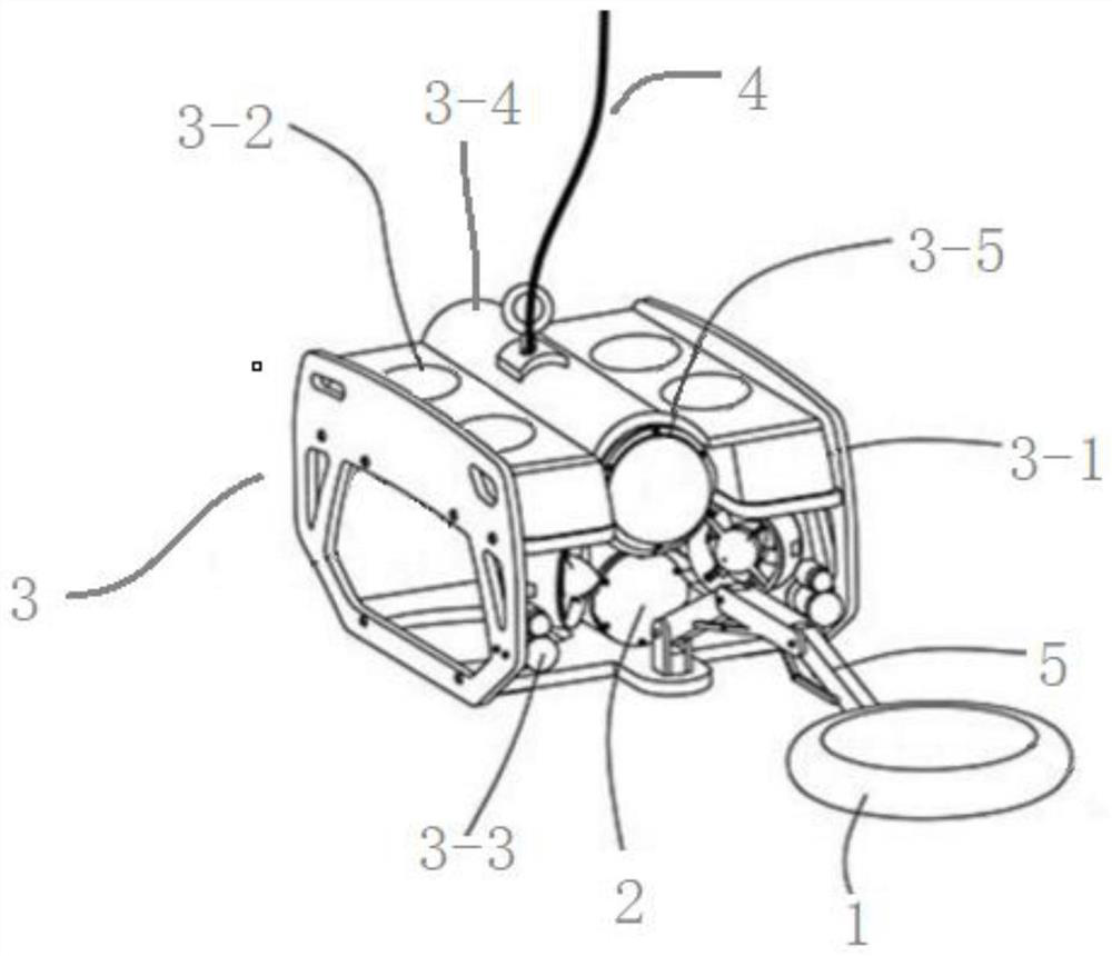
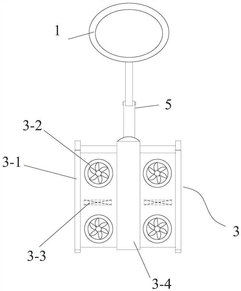
[0071] Such as figure 2 shown, including:

[0072] Transmitting probe 1, the transmitting source is a ring and a pseudo-random sequence or step wave passes through its two ends.

[0073] Receiver 2, at least two receivers 2 are arranged along the axial direction of the transmitting source, remove the system response of the transmitter and the receiver from the received signal, and obtain the pulse signal.

[0074] The working platform 3 is connected to the upper computer and the power supply on the mobile carrier through the cable 4 .

[0075] Specifically, the working platform 3 includes: a frame body 3-1, a lifting module 3-2, a steering module 3-3, and a cylindrical connecting part 3-4, such as figure 2 , 3 As shown, the cylindrical connecting part 3-4 is arranged in the center of the frame body 3-1 and is fixedly connected with the frame body, and the lifting module 3-2 is arranged on th...

Embodiment 2

[0082] Embodiment 2, a multi-channel transient electromagnetic inversion method based on footprint technology, see figure 1 , 6 -15.

[0083] The multi-channel transient electromagnetic inversion method based on the footprint technology disclosed in the embodiment of the present invention is realized by the transient electromagnetic survey device disclosed in the first embodiment.

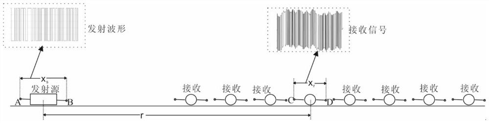
[0084] (1) Specifically, through figure 1 , 6 -8 Describe in detail the working principle of the multi-channel transient electromagnetic method and the process of extracting the ground impulse response. In order to overcome the shortcomings of the original survey method, the present invention uses the multi-channel transient electromagnetic method for surveying. The specific working method is as follows figure 1 , 6 shown.

[0085] Pass a pseudo-random sequence or step wave at the AB end, observe on the axial device (the prior art), and the receiving end usually has multiple receivers during m...


PUM


Abstract

The invention discloses a multi-channel transient electromagnetic inversion method based on a footprint technology and a transient electromagnetic survey device, and the method can greatly reduce thethree-dimensional inversion space corresponding to a single data point, improves the multi-channel transient electromagnetic three-dimensional inversion efficiency, and comprises the following steps:S1, transmitting a pseudo-random coded current; S2, receiving a pseudo-random response containing geological information; S3, obtaining a ground pulse response; S4, loading an inversion area and meshgeneration model parameters; S5, constructing a minimum parameter functional; S6, constructing a footprint weighting matrix, and constructing a footprint weighting matrix; and S7, obtaining the distribution condition of the geoelectric structure in the inversion area. The device comprises a transmitting probe, a receiver and a working platform.

Description

technical field [0001] The invention relates to the fields of oil and gas resources and geophysics, in particular to a footprint technology-based multi-channel transient electromagnetic inversion method and a transient electromagnetic surveying device. Background technique [0002] Multi-Transient Electromagnetic (MTEM) is a new technology developed in the world since 2002. my country's mineral and oil and gas resources are in short supply, and iron, copper, aluminum and potassium salts are highly dependent on foreign imports, which restricts The sustainable development of the national economy; in view of the serious shortage of mineral resource reserves in my country, "deepening and blind exploration" has become the main battlefield for a new round of resource exploration. [0003] However, as the burial depth of the target increases, the detection environment becomes more complex, and the difficulty of detection increases sharply. Taking into account large depth and high-pr...

Claims


Application Information

Patent Timeline
IPC IPC(8): G01V3/08
CPCG01V3/081
Inventor 王显祥邓居智尤农人常永帮
Owner EAST CHINA UNIV OF TECH
Why Eureka
Try Eureka