Supercharge Your Innovation With Domain-Expert AI Agents!

A kind of lens and processing method thereof

A processing method and lens technology, applied in packaging, instruments, optics, etc., can solve the problems of the protective film not fully covering the lens, increase the amount of protective film, and increase the processing cost, so as to improve the lens yield and prevent dust. Effect, effect of low production cost

Active Publication Date: 2022-04-22
东莞市汇铭洋光电有限公司
View PDF10 Cites 0 Cited by
  • Summary
  • Abstract
  • Description
  • Claims
  • Application Information

AI Technical Summary

Problems solved by technology

[0003] The traditional flat lens is cut by CNC, and the protective film needs to be pasted one by one on the front of the lens to meet the factory requirements; but the process of changing the film is difficult to focus, even if the surface area of ​​the protective film used is larger than the front of the lens, the protective film is still easy to appear If the front side of the lens cannot be fully covered, the yield rate will decrease, the efficiency will decrease, and the amount of protective film will be increased, which will increase the processing cost

Method used


Image

  • A kind of lens and processing method thereof
  • A kind of lens and processing method thereof
  • A kind of lens and processing method thereof

Examples


Embodiment 1

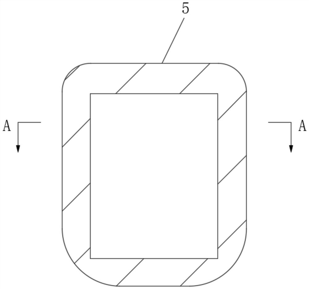
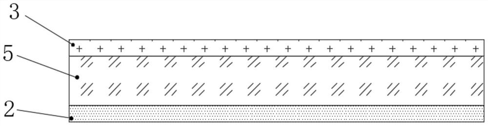
[0043] Such as Figure 1-2As shown, a lens includes a lens body 5, a first protective film 2 attached to the back of the lens body 5, and a second protective film 3 attached to the front of the lens body 5, and the first protective film 2 is close to the lens Acrylic glue is adhered to one side of the body 5 and the side of the second protective film 3 close to the lens body 5 .

Embodiment 2

[0045] The difference between this embodiment and embodiment 1 is:

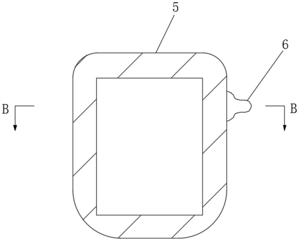
[0046] Such as Figure 3-4 As shown, the second protective film 3 is pasted with a handle portion 6 .

[0047] The handle part 6 includes a primer layer 61 and a PET film 62 bonded to the primer layer 61, the PET film 62 protrudes from the second protective film 3, and the primer layer 61 is sandwiched between the Between the PET film 62 and the second protective film 3 .

Embodiment 3

[0049] Such as figure 1 , 2 , shown in 5, a kind of processing method of eyeglass, comprises the steps:

[0050] (S1), take forming plate 1, set aside;

[0051] (S2), attaching the first protective film 2 to the front and back sides of the formed plate 1;

[0052] (S3), tear off the first protective film 2 on the front of the forming plate 1, and then attach the second protective film 3 and the third protective film on the front of the forming plate 1 in sequence;

[0053] (S4), positioning holes 4 are drilled on both sides of the raw material plate in step (S3), and then the formed plate 1 in step (S3) is CNC cut to form a plurality of evenly distributed semi-finished products;

[0054] (S5), after washing and drying the semi-finished product, tear off the third protective film to obtain the lens.

[0055] The forming sheet 1 is formed by ink printing on the raw sheet according to the layout design, and then drying;

[0056] Wherein, the raw material plate is PMMA plate....


PUM

PropertyMeasurementUnit
hardnessaaaaaaaaaa
transmittivityaaaaaaaaaa

Abstract

The present invention relates to the technical field of lens coating, in particular to a lens and a processing method thereof. The processing method includes the following steps: (S1), taking a forming plate for later use; (S2), attaching the front and back sides of the forming plate The first protective film; (S3), tear off the first protective film on the front of the forming plate, and then attach the second protective film and the third protective film on the front of the forming plate; (S4), to the step (S3) The formed sheet is cut by CNC to form a plurality of uniformly distributed semi-finished products; (S5), after cleaning and drying the semi-finished products, tear off the third protective film to obtain the lens. In this processing method, the second protective film and the third protective film are firstly covered on the front of the forming plate, and then processed into multiple lenses together with the forming plate, which saves the process of attaching films to the lenses one by one in the later stage, and the protective film after CNC cutting and The front of the lens is coincident, so that the protective film fully covers the front of the lens, which greatly improves the yield of the lens.

Description

technical field [0001] The invention relates to the technical field of lens coating, in particular to a lens and a processing method thereof. Background technique [0002] Flat lenses are PMMA or PC lenses obtained by printing and CNC cutting. The main materials are PMMA and PC. If the requirement for the hardness of the lens surface is not high, even raw board (unstrengthened plate) can be directly used as the material of the flat lens to reduce the cost. [0003] The traditional flat lens is cut by CNC, and the protective film needs to be pasted one by one on the front of the lens to meet the factory requirements; but the process of changing the film is difficult to focus, even if the surface area of ​​the protective film used is larger than the front of the lens, the protective film is still easy to appear If the front side of the lens cannot be fully covered, the yield rate will decrease, the efficiency will decrease, and the amount of protective film will be increased,...

Claims


Application Information

Patent Timeline
Patent Type & Authority Patents(China)
IPC IPC(8): B65B33/02G02B1/14
CPCB65B33/02G02B1/14
Inventor 秦伯乐
Owner 东莞市汇铭洋光电有限公司
Features
  • R&D
  • Intellectual Property
  • Life Sciences
  • Materials
  • Tech Scout
  • Unparalleled Data Quality
  • Higher Quality Content
  • 60% Fewer Hallucinations
Learn More