
Capacitance defect detection method based on machine vision

A defect detection and machine vision technology, applied in the direction of optical testing defects/defects, instruments, measuring devices, etc., can solve the problems of restricting the production of enterprises, low detection efficiency, slow detection speed, etc., to ensure consistency, reliability and reliability. The effect of high accuracy and fast detection speed

Active Publication Date: 2020-09-25
湖南恒岳重钢钢结构工程有限公司
View PDF7 Cites 4 Cited by
  • Summary
  • Abstract
  • Description
  • Claims
  • Application Information

AI Technical Summary

Problems solved by technology

[0002] Defects on the surface of capacitors include convex hull defects and concave defects. At present, most capacitor manufacturers still use manual naked eye detection in the detection of capacitor defects. There are problems such as slow detection speed, low detection efficiency, and greater subjectivity. This detection method is not enough to meet the modern production requirements of the enterprise, and has become a bottleneck restricting the production of the enterprise.

Method used


Image

  • Capacitance defect detection method based on machine vision
  • Capacitance defect detection method based on machine vision
  • Capacitance defect detection method based on machine vision

Examples


Embodiment 1

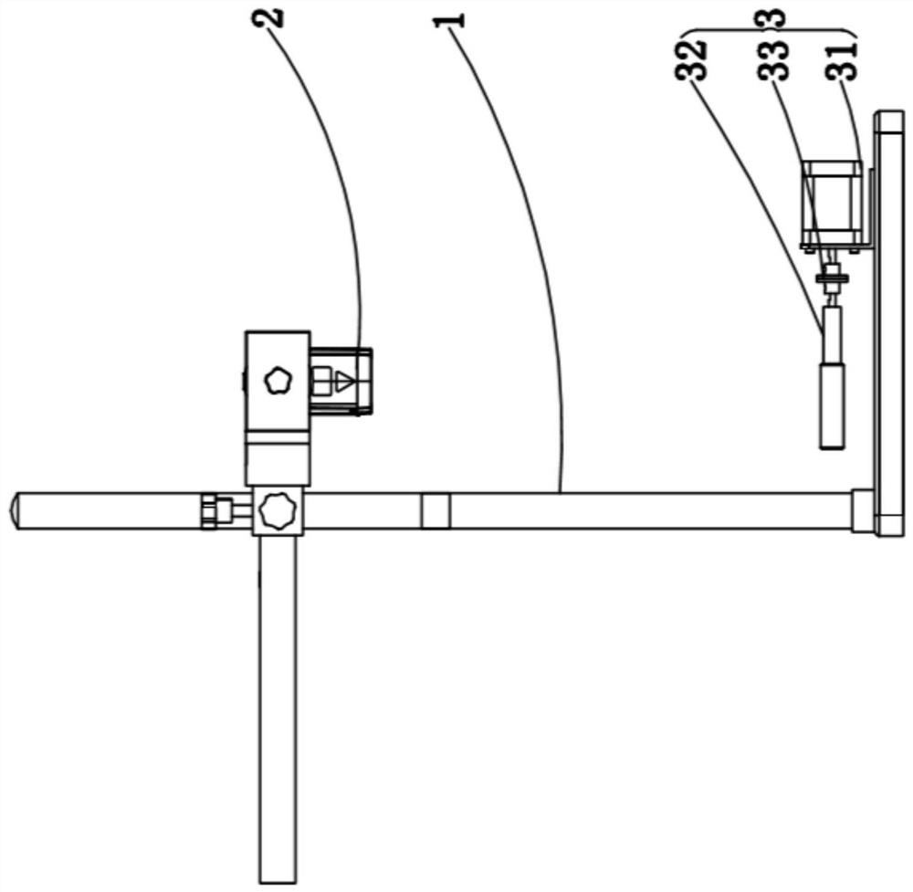
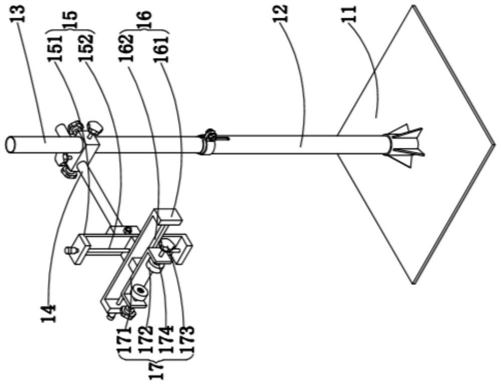
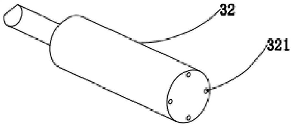
[0057] see Figure 1 to Figure 3 , figure 1 It is a schematic structural diagram of the machine vision-based capacitive defect detection device of this embodiment; figure 2 It is a structural schematic diagram of the camera bracket of the capacitive defect detection device based on machine vision in this embodiment; image 3It is a structural schematic diagram of the capacitance fixture of this embodiment. As shown in the figure, this embodiment provides a defect detection device. The defect detection device of this embodiment includes an image acquisition system, a motion control system and a defect detection system. The image acquisition system includes a camera bracket 1, a laser camera 2 and a computer ( Not shown in the figure), the camera bracket 1 is used to fix the laser camera 2, and the laser camera 2 is used to collect the image data of the capacitor to be detected and transmit the image data to the computer. The image data taken include height map and depth map;...

Embodiment 2

[0068] see Figure 4 , Figure 4 It is a flow chart of the detection method of this embodiment. As shown in the figure, the defect detection method based on machine vision adopts the defect detection device described in Embodiment 1, and the specific detection method is as follows:

[0069] Step A. Image Data Acquisition:

[0070] Fix the capacitor to the motion control system: insert the electrode of the capacitor to be detected into the opening 321 of the capacitor fixture 32, so that the capacitor fixture 32 fixes the capacitor to be detected;

[0071] Motion control system rotation capacitor: the motion control card controls the rotation of the stepper motor 31, and the motion control card sends a rotation pulse signal to the stepper driver. When the stepper driver receives the rotation pulse signal from the motion control card, it will drive the stepper motor 31 rotates one revolution, thereby driving the capacitor to rotate one revolution;

[0072] The image acquisit...


PUM


Abstract

The invention discloses a capacitance defect detection method based on machine vision. The detection method comprises the following steps: step A, image data acquisition: a capacitor is fixed to a motion control system; the motion control system rotates the capacitor; the image acquisition system acquires image data of the surface of the capacitor in the rotating process of the capacitor to obtaina height map and a depth map of the surface of the capacitor; the image acquisition system preprocesses and outputs the image data; B, a capacitor surface coding template is created; and C, defect detection. Compared with the prior art, the capacitor defect detection method has the advantages that the type of the capacitor can be detected, convex hull defects and concave defects on the surface ofthe capacitor can be detected, and only when the type of the capacitor is detected to be qualified, the defect detection system can carry out encapsulation position detection; only when the encapsulation position is detected to be qualified, the defect detection system can detect the surface defects of the capacitor, so that the consistency of the capacitor can be ensured, the capacitor defects can be detected, the reliability and accuracy are high, and the detection speed is high.

Description

technical field [0001] The invention relates to the technical field of capacitance defect detection, in particular to a method for detecting capacitance defects based on machine vision. Background technique [0002] Defects on the surface of capacitors include convex hull defects and concave defects. At present, most capacitor manufacturers still use manual naked eye detection in the detection of capacitor defects. There are problems such as slow detection speed, low detection efficiency, and greater subjectivity. This detection method is not enough to meet the modern production requirements of the enterprise, and has become a bottleneck restricting the production of the enterprise. Contents of the invention [0003] The purpose of the invention is to provide a method for detecting capacitive defects based on machine vision, which is used to solve the above technical problems. [0004] A capacitance defect detection method based on machine vision, based on a defect detect...

Claims


Application Information

Patent Timeline
Patent Type & Authority Applications(China)
IPC IPC(8): G06T7/00G01N21/88
CPCG06T7/0006G06T7/001G01N21/8851G06T2207/10028G01N2021/8887
Inventor 肖苏华罗文斌吴建毅曹应斌赖南英刘宁何林聪林锐豪
Owner 湖南恒岳重钢钢结构工程有限公司
Learn More