A photoelectric edge detection system and its detection method
An edge detection, photoelectric technology, applied in the field of photoelectric edge detection system, can solve the problems of stability of light power change, probe wear material, low sensitivity, etc. high effect
- Summary
- Abstract
- Description
- Claims
- Application Information
AI Technical Summary
Problems solved by technology
Method used
Image
Examples
Embodiment 1
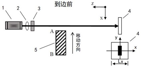
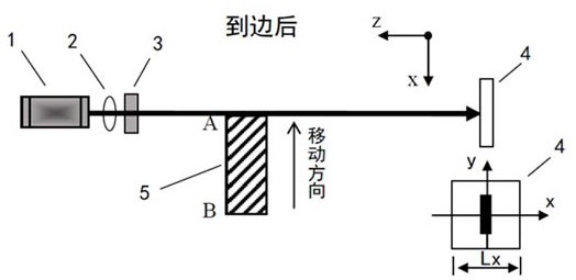
[0042] Embodiment 1: as figure 1 As shown, a photoelectric edge detection system includes a light source 1, the light source 1 cooperates with a diaphragm 3 through a collimator 2, and the diaphragm 3 cooperates with a position-sensitive photodetector 4. The object to be measured is made of low transmittance material. The light source 1, collimator 2, aperture 3 and position sensitive photodetector 4 are located on both sides of the object to be measured. The light overlaps and is arranged perpendicular to the photosensitive surface of the position-sensitive photodetector 4. The position-sensitive photodetector 4 is connected to the signal processing unit. The signal processing unit includes a signal processing circuit and a single-chip microcomputer / host computer. The position-sensitive photodetector outputs The photoelectric current signal is transmitted to the single-chip microcomputer or host computer through the signal processing circuit.
Embodiment 2
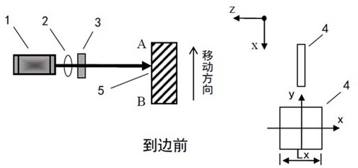
[0043] Embodiment 2: as Figure 5 As shown, a photoelectric edge detection system, when the object 5 to be measured is a material with high transmittance, such as glass, or an object whose surface is mirror-reflected such as a liquid crystal screen, the position of the light source 1, the collimator 2 and the diaphragm 3 The sensitive photodetector 4 is located on the same side of the object to be measured. According to the axis of the collimator 2 and the axis of the diaphragm 3 coincide with the light emitted by the light source 1, the light is incident on the surface of the object to be measured, and after reflection, it is vertically incident on the position-sensitive photoelectric detector. Arrangement in the center of the photosensitive surface of the device;
[0044] All the other structures are the same as in Example 1.
Embodiment 3
[0045] Embodiment 3: a kind of photoelectric edge detection method, comprises the following steps:
[0046] S1, the light source 1 emits light, the light source 1, the collimator 2, the diaphragm 3 and the position sensitive photodetector 4 are arranged in sequence along the light, the light emitted by the light source 1 coincides with the axis of the collimator 2 and the axis of the diaphragm 3, Vertical to the photosensitive surface of the position sensitive photodetector 4;
[0047] S2. The light emitted by the light source 1 passes through the collimator 2 to obtain a collimated beam. The collimated beam is shaped by the diaphragm 3. Straight beam cross-section forms a spot of set size and shape;
[0048] When the edge of the object 5 to be measured is a straight line, a rectangular aperture is selected. For edges of other characteristic types such as arcs, the corresponding specific shape aperture 3 can also be selected for beam shaping;
[0049] S3. The shaped collimat...
PUM
 Abstract
Description
Claims
Application Information
 - R&D
- Intellectual Property
- Life Sciences
- Materials
- Tech Scout
- Unparalleled Data Quality
- Higher Quality Content
- 60% Fewer Hallucinations
Browse by: Latest US Patents, China's latest patents, Technical Efficacy Thesaurus, Application Domain, Technology Topic, Popular Technical Reports.
© 2025 PatSnap. All rights reserved.Legal|Privacy policy|Modern Slavery Act Transparency Statement|Sitemap|About US| Contact US: help@patsnap.com


