
Mode division multiplexer, mode division multiplexing system, demultiplexing system and communication system

A mode-division multiplexer and mode-division multiplexing technology, which is applied in the field of communication, can solve the problems of large crosstalk, large pixel size of the phase plate, and low resolution, and achieve small crosstalk, low energy loss, and good signal transmission effect Effect

Active Publication Date: 2020-09-29
HUAWEI TECH CO LTD
View PDF5 Cites 7 Cited by
  • Summary
  • Abstract
  • Description
  • Claims
  • Application Information

AI Technical Summary

Problems solved by technology

Among them, multi-plane light conversion is regarded as the most potentially valuable application technology, but in the existing multi-plane light conversion devices, it is generally realized by setting phase plates or spatial light modulators at multiple discrete planes. The continuous conversion of the spatial light transmission wavefront, but due to the large pixel size of the spatial light modulator and the phase plate, there are problems such as low resolution and large crosstalk in the process of wavefront conversion (that is, the process of spatial mode conversion of the beam)

Method used


Image

  • Mode division multiplexer, mode division multiplexing system, demultiplexing system and communication system
  • Mode division multiplexer, mode division multiplexing system, demultiplexing system and communication system
  • Mode division multiplexer, mode division multiplexing system, demultiplexing system and communication system

Examples


Embodiment Construction

[0052] The technical solutions in the embodiments of the present application will be clearly and completely described below in conjunction with the drawings in the embodiments of the present application.

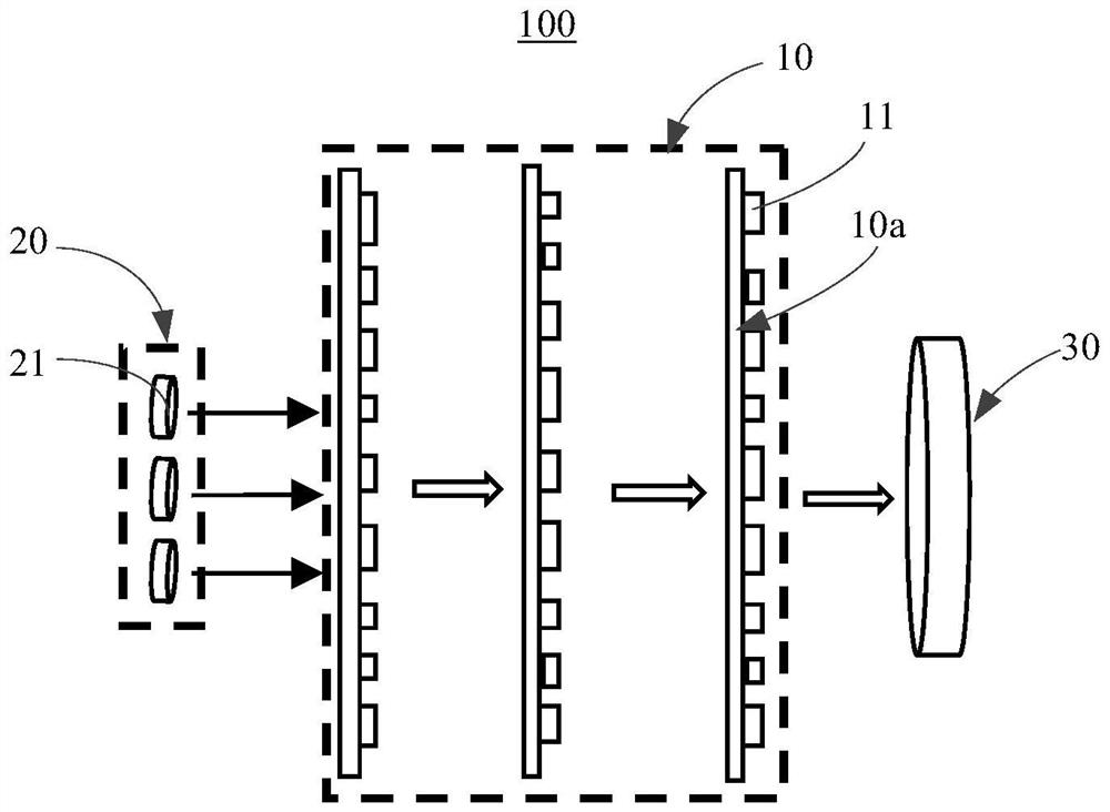
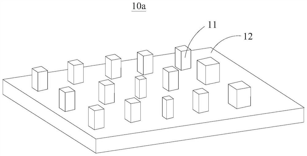
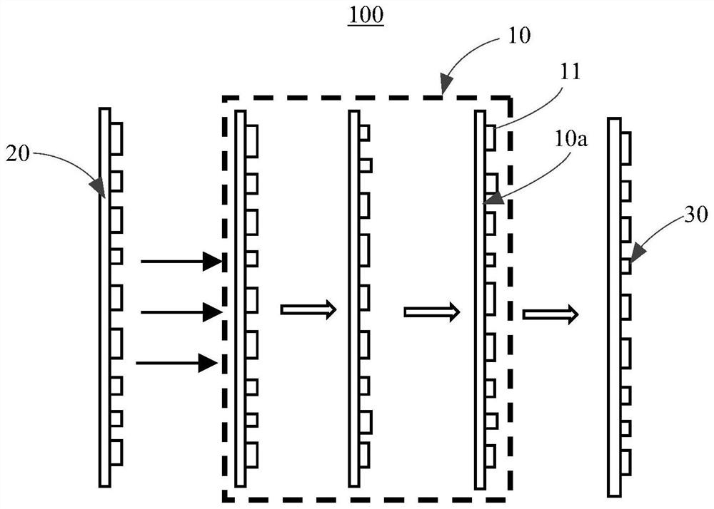
[0053] The present application provides a mode division multiplexer, and the mode division multiplexer is generally used in a space division multiplexing system (including a mode division multiplexing system, a mode division multiplexing system, etc.) to increase optical communication capacity. see figure 1 and figure 2 , the present application provides a mode division multiplexer 100 . in, figure 1 The arrow direction in is the transmission direction of the light beam in the mode division multiplexer 100 in this embodiment. In this application, the working band of the mode division multiplexer is located in the optical fiber communication band. The mode division multiplexer 100 includes a first collimator 20, a second collimator 30, and a mode division multiplexing mo...


PUM


Abstract

The invention provides a mode division multiplexer, a mode division multiplexing system comprising the mode division multiplexer, a demultiplexing system comprising the mode division multiplexer, anda communication system comprising the mode division multiplexing system and the demultiplexing system. The mode division multiplexer includes a metasurface having a plurality of sub-wavelength electromagnetic resonance units arranged in an array. Each electromagnetic resonance unit is used for carrying out phase modulation on the light beam transmitted to the electromagnetic resonance unit so as to convert the spatial mode order of the light beam. Since the size of the electromagnetic resonance units is sub-wavelength, the size of the electromagnetic resonance units is smaller than the pixel size of a spatial light modulator in the prior art, crosstalk of different spatial modes after phase modulation of the mode division multiplexer is low, and crosstalk is low when light beams of different spatial modes are multiplexed in at least mode / multimode optical fibers. Meanwhile, compared with the polarization dependence problem of the spatial light modulator in the prior art, the mode division multiplexer provided by the invention can realize polarization-independent phase modulation.

Description

technical field [0001] The present application relates to the technical field of communication, and in particular to a mode division multiplexer, a mode division multiplexing system, a demultiplexing system and a communication system. Background technique [0002] In recent years, with the rapid development of emerging services such as high-definition video, the Internet of Things, and cloud computing, people's demand for bandwidth continues to increase. At present, single-mode fiber has approached its theoretical transmission limit, and space division multiplexing technology is expected to greatly improve the capacity of optical fiber communication by using its new spatial multiplexing dimension, and then break through the theoretical transmission limit of single-mode fiber. Mode-division multiplexing, as a type of space-division multiplexing technology, has attracted widespread attention in recent years. It uses independent orthogonal modes in few-mode / multi-mode fibers as...

Claims


Application Information

Patent Timeline
IPC IPC(8): G02B6/293
CPCG02B6/293H04J14/04H04J14/052G02B6/2848G02B6/26G02B6/29304H04B10/2581H04J14/06
Inventor 殷祥王勇罗辑
Owner HUAWEI TECH CO LTD
Learn More