Excavator movable arm energy-saving system

A technology of energy-saving system and motorized arm, which is applied to fluid pressure actuating system components, mechanically driven excavators/dredgers, earthmoving machines/shovels, etc., which can solve the problem of reduced practicability, high cost, and overall energy-saving system. high cost problem

Active Publication Date: 2020-10-02
XUZHOU COLLEGE OF INDAL TECH
View PDF7 Cites 2 Cited by
  • Summary
  • Abstract
  • Description
  • Claims
  • Application Information

AI Technical Summary

Problems solved by technology

[0005] In some schemes that use hydraulic pump motors as energy conversion components, it is often required that the hydraulic pump motor has a bidirectional rotation function and the swash plate has a neutral zero crossing function. This hydraulic pump motor can switch the working

Method used


Image

  • Excavator movable arm energy-saving system
  • Excavator movable arm energy-saving system
  • Excavator movable arm energy-saving system

Examples


Embodiment 1

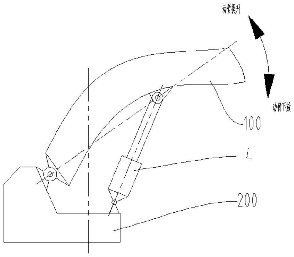
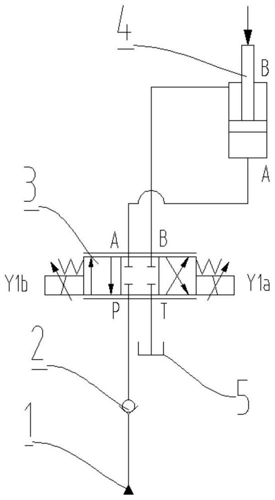
[0052] Such as Figure 4 , Figure 6 and Figure 7 As shown, an excavator arm energy-saving system includes an oil source 1, a first one-way valve 2, a main reversing valve 3, a boom hydraulic cylinder 4, a joystick of an excavator, a fifth one-way valve 17, a hydraulic pressure Motor 6, accumulator 10, gearbox 8, first reversing valve 11, clutch 9, flywheel 7, second one-way valve 13, third one-way valve 14, fourth one-way valve 16, speed detection device and Controller; the oil source 1 is connected to the P port of the main reversing valve 3 through the first one-way valve 2, and the T port of the main reversing valve 3 is connected to the oil tank 5; the A port and the B port of the main reversing valve 3 are respectively connected to The rodless chamber of the boom hydraulic cylinder 4 is connected to the rod chamber; the cylinder barrel of the boom hydraulic cylinder 4 is hinged on the turntable 200, and the piston rod end of the boom hydraulic cylinder 4 is hinged at ...

Embodiment 2

[0068] Such as Figure 5 to Figure 7 As shown, an excavator arm energy-saving system includes an oil source 1, a first one-way valve 2, a main reversing valve 3, a boom hydraulic cylinder 4, a joystick of an excavator, a hydraulic motor 6, and an accumulator 10 , gearbox 8, first reversing valve 11, clutch 9, flywheel 7, second one-way valve 13, third one-way valve 14, fourth one-way valve 16, speed detection device and controller;

[0069] The oil source 1 is connected to the P port of the main reversing valve 3 through the first check valve 2, and the T port of the main reversing valve 3 is connected to the oil tank 5; the A port and the B port of the main reversing valve 3 are respectively connected to the boom hydraulic pressure The rodless chamber of the cylinder 4 is connected to the rod chamber; the cylinder barrel of the boom hydraulic cylinder 4 is hinged on the turntable 200, and the piston rod end of the boom hydraulic cylinder 4 is hinged at the middle of the boom ...

no. 1 example

[0102] 1. Energy recovery process

[0103] Assume that the boom hydraulic cylinder 4 has been stretched out at this time, and the boom 100 is at a higher position. When the boom 100 needs to be lowered, the operator sends a discharge signal under the boom to the controller through the corresponding button on the joystick, and the controller (not shown) controls the solenoid valve of the main reversing valve 3 after receiving the discharge signal under the boom. Iron Y1a, the electromagnet of the first reversing valve 11 and the clutch 9 are energized, and send a control signal X to the linear electric push rod 806 to control its extension to a set length, so that the gearbox 8 is switched to the working gear state A, and the working Gearbox 8 is the state of forward rotation during gear state A. At the same time, the controller sends a control signal A to the hydraulic motor 6 to adjust its displacement. The oil source 1 enters the rod cavity of the boom hydraulic cylinder 4...


PUM


Abstract

The invention relates to an excavator movable arm energy-saving system. A port P of a hydraulic motor is connected with a rodless cavity of a movable arm hydraulic cylinder through a first reversing valve, a port A of the hydraulic motor is connected with an energy accumulator, and a transmission shaft of the hydraulic motor is connected with a flywheel through a gearbox and a clutch; a port B ofa second one-way valve and a port A of a third one-way valve are connected with a port A of the first reversing valve; a port A of the second one-way valve and a port B of the third one-way valve arecorrespondingly connected with an oil tank and a port P of the main reversing valve; a gearbox comprises a box body, a first transmission shaft unit, a second transmission shaft unit, a sliding blockassembly, a shifting fork and a linear electric push rod, and the first transmission shaft unit comprises a first transmission shaft, a first bevel gear A, a shaft sleeve A, a third gear A, a fourth gear A, a shaft sleeve B and a second bevel gear A; the second transmission shaft unit comprises a second transmission shaft, a first bevel gear B and a second bevel gear B; and the sliding block assembly comprises a sliding block body, a first transition gear ring and a second transition gear ring. The system can reduce the manufacturing cost of a recovery system.

Description

technical field [0001] The invention belongs to the technical field of hydraulic transmission, and in particular relates to an energy-saving system for an excavator arm. Background technique [0002] Hydraulic excavators are widely used in various construction fields. Hydraulic excavators have disadvantages such as high fuel consumption and low efficiency. Research on energy saving is imminent. [0003] figure 1 It is a structural schematic diagram of a common excavator at present. Wherein, the end of the boom 100 is hinged on the turntable 200 , the cylinder barrel of the boom hydraulic cylinder 101 is hinged on the turntable 200 , and the piston rod end of the boom hydraulic cylinder 101 is hinged on the middle of the boom 100 . When the piston rod of the boom hydraulic cylinder 101 performs telescopic movement, it can drive the boom 100 to perform lifting and lowering actions. During the working process of the excavator, the boom lifts frequently, and due to the large ...

Claims


Application Information

Patent Timeline
IPC IPC(8): E02F3/42E02F9/22F16H3/32F16H3/40F15B21/14F15B1/02F15B11/08
CPCE02F3/42E02F9/22E02F9/2217E02F9/2264E02F9/2267F16H3/002F16H3/32F16H3/40F15B21/14F15B1/02F15B11/08
Inventor 李建松许大华张文婷
Owner XUZHOU COLLEGE OF INDAL TECH
Why Eureka
Try Eureka