
Grout sleeve for steel bar connection and machining process of grout sleeve

A technology of grouting sleeve and processing technology, which is applied in the direction of building reinforcements, structural elements, building components, etc., can solve the problem of uneven stress on a single spiral shear groove, difficulty in changing the temperature of the grouting sleeve, and reduce sleeve grouting Improve the quality of grouting construction, reduce processing defects, and reduce construction costs

Pending Publication Date: 2020-10-02
武汉合创炬盛科技有限公司
View PDF0 Cites 0 Cited by
  • Summary
  • Abstract
  • Description
  • Claims
  • Application Information

AI Technical Summary

Problems solved by technology

In order to improve the gripping force of the grouting sleeve on the grouting material in the inner cavity, a point-shaped, one-shaped, eight-shaped, annular or spiral boss is generally arranged on the inner wall of the grouting sleeve to increase the inner shear of the grouting sleeve. The mechanical bite force between the force key and the grouting material of the sleeve, so as to realize the force transmission capacity of the joint, the shear grooves distributed in short lines or dots are easy to form stress defects on the grouting sleeve body; the shear grooves distributed in a ring are easy to Throttling is formed at the corner to reduce the density of sleeve grouting material; single helical shear groove is prone to the disadvantage of uneven force; double helix or multi-helix structure shear groove makes processing more difficult, so the above forms of shear There are more or less problems with the force tank
[0004] In addition, the construction of steel sleeve grouting connection is significantly affected by temperature, especially in winter and summer construction, it is necessary to improve and optimize the formula of sleeve grouting material, or use heated water stirring, external heating and heat preservation of prefabricated components, and heat preservation during grouting construction. Auxiliary measures such as ice water cooling, but due to the small specific heat capacity of concrete, it is difficult to change the internal temperature of the grouting sleeve, and the gap between the inner wall of the grouting sleeve and the outer wall of the connected straight thread steel bar is very small, resulting in the grouting sleeve The sleeve grouting material is extremely affected by the ambient temperature

Method used


Image

  • Grout sleeve for steel bar connection and machining process of grout sleeve
  • Grout sleeve for steel bar connection and machining process of grout sleeve
  • Grout sleeve for steel bar connection and machining process of grout sleeve

Examples


Embodiment 1

[0051] Using nodular cast iron to make the grouting sleeve 4 includes the following steps,

[0052] S1. Make grouting sleeve 4 modules and sand cores, and then make sand boxes;

[0053] S2. Smelting nodular cast iron according to the formula adjusted to meet the mechanical performance requirements to make molten iron, pouring and forming the grouting sleeve 4, turning over the casting after the casting is cooled to the requirements, and performing shot blasting and correction polishing;

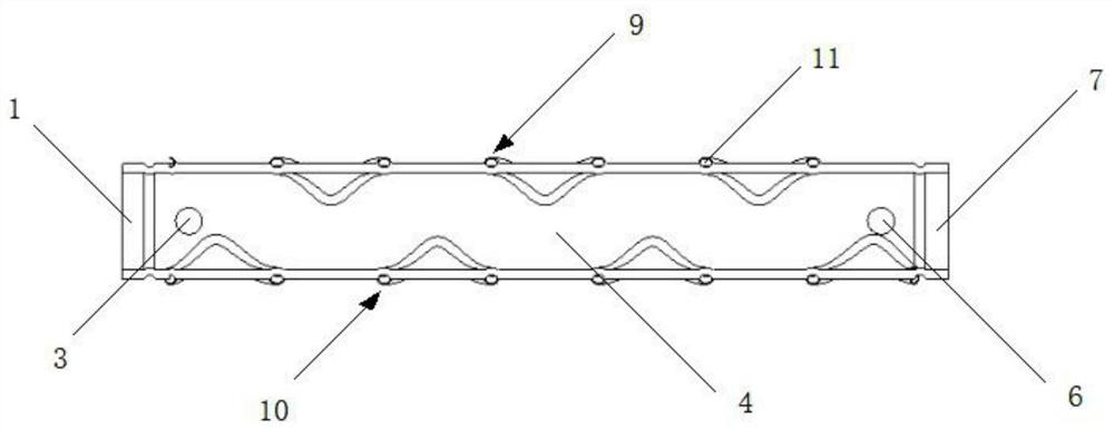
[0054] S3. For the grouting sleeve 4 whose prefabricated installation end 7 is threaded, after the prefabricated installation end 7 is internally threaded, the upper groove pattern 9 and the lower groove pattern 10 are closely attached to the heat exchange circulation pipeline 11 , to complete the processing technology;

[0055] S4. For the grouting sleeve 4 connected by grouting at the prefabricated installation end 7, after the prefabricated installation end 7 does not need to be tapped, t...

Embodiment 2

[0057] Using a seamless steel pipe to make the grouting sleeve 4 includes the following steps,

[0058] S1. Cut the seamless steel pipe to the design length, and use the button mold to extrude to form the annular groove, the upper groove pattern 9, the lower groove pattern 10 and the wave-shaped boss 8;

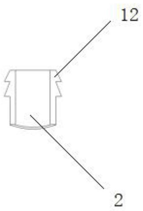
[0059] S2. Use a punching machine to punch holes at designated positions to form a slurry inlet through hole 2 and a slurry outlet through hole 5, install the slurry inlet conduit 3 with an annular protrusion at the slurry inlet through hole 2 and weld it firmly, and place the slurry inlet conduit 3 with an annular protrusion The slurry outlet conduit 6 is installed and fixed at the slurry outlet through hole 5;

[0060] S3. The upper groove pattern 9 and the lower groove pattern 10 are closely attached to the heat exchange circulation pipeline 11 to complete the processing technology.

Embodiment 3

[0062] Using a seamless steel pipe to make the grouting sleeve 4 includes the following steps,

[0063] S1. Cut the seamless steel pipe to the design length, clamp the seamless steel pipe in the mold in the hydraulic pliers of the reducing machine, and form annular grooves, upper groove lines 9, and lower groove lines through extrusion of the mold in the hydraulic pliers 10 and wave-shaped boss 8;

[0064] S2. Reduce the outer diameter of the prefabricated installation end 7 to the design value through secondary diameter reduction; perform internal thread tapping on the prefabricated installation end 7 to meet the design requirements; use a punching machine to punch holes at the designated position to form the through hole 2 and the pulp outlet through hole 5;

[0065] S3. Install the slurry inlet conduit 3 with the annular protrusion on the slurry inlet through hole 2 and weld it firmly, install the slurry outlet conduit 6 with the annular protrusion on the slurry outlet thr...


PUM


Abstract

The invention relates to the technical field of steel bar sleeve grouting and discloses a grout sleeve for steel bar connection. The grout sleeve comprises an on-site assembling end and a prefabricated mounting end which are sequentially arranged in the grout flowing direction, wherein the on-site assembling end is provided with a feeding through hole, and the prefabricated mounting end is provided with a discharging through hole; a feeding conduit is fixed to the feeding through hole, and a discharging conduit is fixed to the discharging through hole; two wavy bosses are arranged on the innerwall of a grout sleeve body and are distributed at the two sides of a longitudinal section of the grout sleeve body in spatial symmetry along a longitudinal line; and upper groove lines are arrangedabove a transverse section of the outer wall of the grout sleeve body, lower groove lines are arranged below the transverse section of the outer wall of the grout sleeve body, and heat exchange circulating pipelines are tightly attached to the upper groove lines and the lower groove lines respectively. According to the grout sleeve, bubbles introduced in the grout construction process can be smoothly discharged, the universality of stress of a grout connecting joint of the steel bar sleeve is improved, the machining difficulty of the grout sleeve is lowered, the process is simple, the universality is high, and the requirement for construction in winter and summer can be met.

Description

technical field [0001] The invention relates to the technical field of steel bar sleeve grouting, in particular to a grouting sleeve for steel bar connection and a processing technology thereof. Background technique [0002] The prefabricated concrete structure is one of the effective forms to realize the industrialization of construction. As the key of the prefabricated concrete structure, node connection directly affects the implementation of the industrialization of construction. As a joint connection form of prefabricated concrete structure, the grouting sleeve for steel bar connection has a great impact on the safety and stability of the structure. [0003] At present, the grouting sleeves on the market are mainly manufactured by casting and machining processes, and the two materials have their own advantages and disadvantages. Therefore, in the current market, grouting sleeves of two materials exist at the same time. In order to improve the gripping force of the grout...

Claims


Application Information

Patent Timeline
Patent Type & Authority Applications(China)
IPC IPC(8): E04C5/18B23P15/00
CPCB23P15/00E04C5/165E04C5/18
Inventor 杨国刚黄键朱海军
Owner 武汉合创炬盛科技有限公司
Learn More