
Carbon dioxide heat pump air conditioning system based on solar power generation defrosting

A carbon dioxide and heat pump air-conditioning technology, applied in air-conditioning systems, household heating, heating methods, etc., can solve the problems of reducing the operating efficiency of air-cooled heat pump units, increasing the thermal resistance of heat exchange tubes and wind side resistance, and reducing heat transfer. Achieve the effect of meeting the complex and changeable working environment requirements, improving energy utilization and heating efficiency

Pending Publication Date: 2020-10-02
ZHENGZHOU UNIV
View PDF0 Cites 0 Cited by
  • Summary
  • Abstract
  • Description
  • Claims
  • Application Information

AI Technical Summary

Problems solved by technology

However, due to the heating operation of the air-conditioning heat pump unit in winter, when the surface temperature of the outdoor finned heat exchange tube is lower than the atmospheric dew point temperature, frosting will occur, and the phenomenon is especially serious when the relative humidity is high
When the frost layer on the surface of the finned tube reaches a certain thickness, it will increase the thermal resistance and wind side resistance of the heat exchange tube, greatly reducing the operating efficiency of the air-cooled heat pump unit, reducing the amount of heat exchange, and increasing energy consumption.

Method used


Image

  • Carbon dioxide heat pump air conditioning system based on solar power generation defrosting

Examples


Embodiment Construction

[0013] The present invention is mainly suitable for cooling and cooling in summer and heating in winter, and the implementation and working process of the above two situations will be explained in detail below.

[0014] Summer conditions:

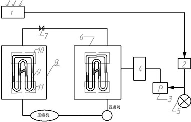
[0015] The working conditions in summer are mainly used for refrigeration and cooling. (1) In summer, after the air conditioner is powered on, the low-pressure steam of the refrigerant in the refrigeration system is sucked by the compressor and compressed into high-pressure steam and then discharged to the condenser. The indoor air circulates continuously to achieve the purpose of lowering the temperature. (2) In summer solar power generation, the electric energy distributed by the accumulator can be used for bathroom lighting or corridor lighting at night, which has the characteristics of energy saving and environmental protection.

[0016] Winter conditions:

[0017] (1) The winter working condition is mainly through the carbon dioxide ...


PUM


Abstract

The invention discloses a carbon dioxide heat pump air conditioning system based on solar power generation defrosting, which comprises a solar power system and a carbon dioxide heat pump air conditioning system, wherein the solar power system comprises a solar panel, an electricity storage device, an LED lamp and a defrosting device, wherein the solar energy is utilized to generate electricity, and defrosting and lighting are reasonably distributed through the electricity storage device. The carbon dioxide heat pump air conditioning system comprises an evaporator, a condenser, an expansion valve and a compressor, wherein each of the evaporator and the condenser is provided with a pulsating heat pipe with a communication path, so that the heating effect in winter and the refrigeration effect in summer are strengthened. The carbon dioxide heat pump air conditioning system uses carbon dioxide as a working medium, and has the advantages of energy conservation and environmental protection and low operation cost. Each of the condenser and the evaporator adopts the pulsating heat pipe of a communication structure, and the main breakthroughs in two aspects are as follows: the first is theoptimization of the communication structure of the pulsating heat pipe, so that an effect of strengthening the heat transfer is achieved; and the second is the change of a placement inclination angleof each pulsating heat pipe, so that the complicated and changeable working environment requirements can be met. Therefore, the power consumption of the whole air conditioner can be reduced, the heatexchange efficiency is increased, the energy utilization rate is improved, and the energy conservation and emission reduction are realized.

Description

technical field [0001] The invention relates to the field of new energy utilization, in particular to a defrosting based on solar power generation, a pulsating heat pipe equipped with a connecting channel, and a carbon dioxide heat pump air conditioning system. Background technique [0002] With the continuous development of society and the improvement of people's living standards, air-conditioning provides people with refreshment in hot summer and heating in cold winter. Therefore, air-conditioning is becoming more and more important in life. However, due to the heating operation of the air-conditioning heat pump unit in winter, when the surface temperature of the outdoor finned heat exchange tube is lower than the atmospheric dew point temperature, frosting will occur, and the phenomenon is especially serious when the relative humidity is high. When the frost layer on the surface of the finned tube reaches a certain thickness, it will increase the thermal resistance and wi...

Claims


Application Information

Patent Timeline
IPC IPC(8): F24F5/00F24F13/30F25B47/00F25B49/02F28D15/02
CPCF24F5/001F24F13/30F25B47/00F25B49/02F28D15/02F24F2005/0039
Inventor 张东伟周俊杰何转桃蒋二辉沈超孟祥睿秦翔史海路
Owner ZHENGZHOU UNIV
Learn More