Fabricated building construction carbon emission treatment system

A treatment system and carbon emission technology, applied in gas treatment, fixed filter element, combustion method, etc., can solve the problems of greenhouse effect, impact on the earth's ecological environment, low practicability, etc., to improve environmental protection and practicability , the effect of increasing carbon dioxide content

Inactive Publication Date: 2020-10-13
NANJING TECH UNIV
View PDF8 Cites 1 Cited by
  • Summary
  • Abstract
  • Description
  • Claims
  • Application Information

AI Technical Summary

Problems solved by technology

[0003] In the construction of buildings, a large amount of greenhouse gases will be produced. If these gases are not dealt with, it will cause the greenhouse effect and seriously affect the ecological environment of the earth.
With the continuous enhancement of people's awareness of environmental protection, people's requirements for carbon dioxide treatment are getting higher and higher. Many construction projects will specially establish a carbon emission treatment system. However, in the existing technology, the treatment of carbon dioxide is only absorption. This carbon dioxide is then treated centrally, which is less practical

Method used


Image

  • Fabricated building construction carbon emission treatment system
  • Fabricated building construction carbon emission treatment system
  • Fabricated building construction carbon emission treatment system

Examples


Embodiment Construction

[0021] The following will clearly and completely describe the technical solutions in the embodiments of the present invention with reference to the accompanying drawings in the embodiments of the present invention. Obviously, the described embodiments are only some, not all, embodiments of the present invention. Based on the embodiments of the present invention, all other embodiments obtained by persons of ordinary skill in the art without making creative efforts belong to the protection scope of the present invention.

[0022] In the description of the present invention, it should be noted that the orientations or positional relationships indicated by the terms "upper", "lower", "inner", "outer", "top / bottom" etc. are based on the orientations shown in the drawings Or positional relationship is only for the convenience of describing the present invention and simplifying the description, but does not indicate or imply that the device or element referred to must have a specific ...


PUM


Abstract

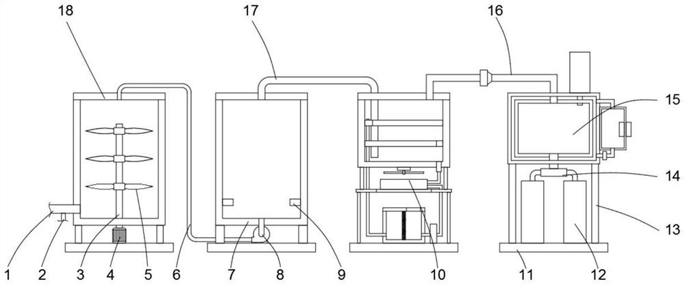
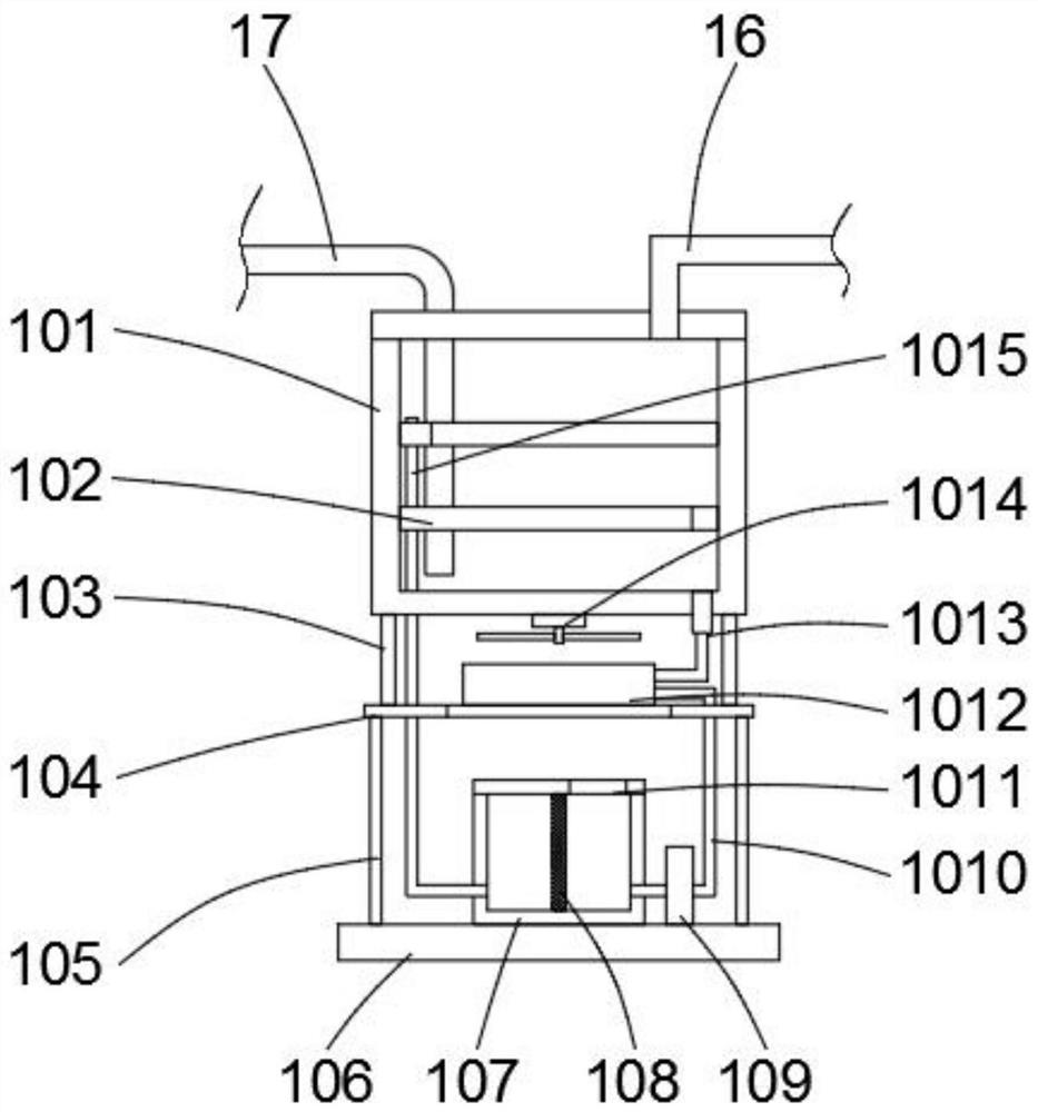
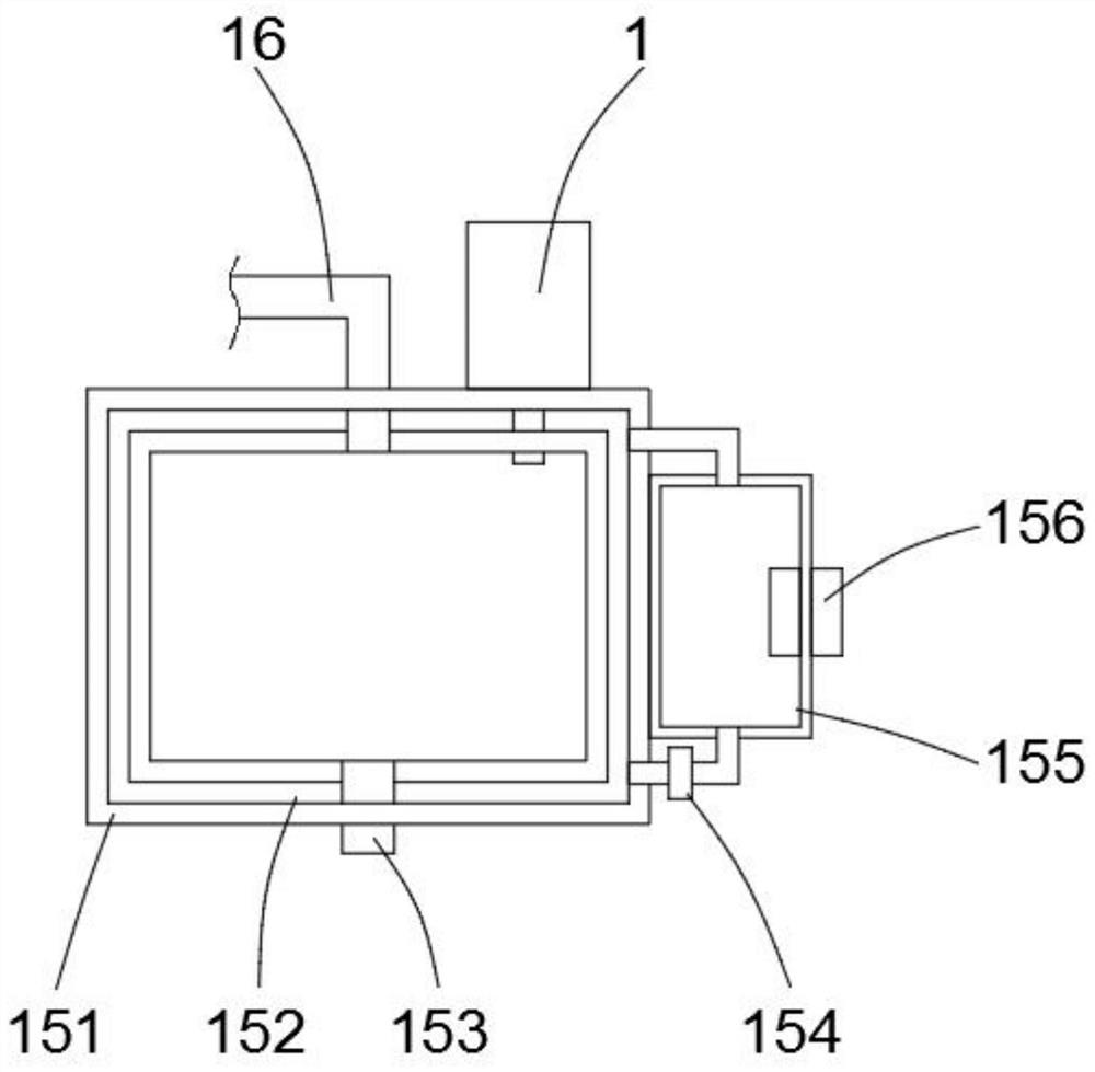
The invention discloses a fabricated building construction carbon emission treatment system, and relates to the technical field of environmental protection. The system mainly comprises a mixing tank,a combustion tank, a desulfurization device and a liquefaction device, wherein the bottom of the mixing tank and the bottom of the combustion tank are fixed on the ground through foot supports, a waste gas pipe is arranged at the bottom of one side of the mixing tank, an oxygen pipe is arranged on the side surface of the waste gas pipe, the top of the mixing tank is connected with an induced draftfan mounted at the bottom of the combustion tank through a first ventilation pipe, the output end of the induced draft fan vertically and upwards extends into the bottom of the combustion tank, the top of the combustion tank is fixedly connected with one end of a second ventilation pipe, the other end of the second ventilation pipe is fixedly connected with the desulfurization device, and the desulfurization device is communicated with the liquefaction device through a third ventilation pipe. In the implementation process of the system, the carbon dioxide is combusted, so that the treatment efficiency of the carbon dioxide is effectively improved, the carbon dioxide is liquefied, the effect of change waste materials into things of value is achieved, and the practicability of the treatmentsystem is effectively improved.

Description

technical field [0001] The invention relates to the technical field of environmental protection, in particular to a prefabricated building construction carbon emission processing system. Background technique [0002] Carbon emissions generally refer to the emission of greenhouse gases, which cause the greenhouse effect and increase the global temperature. While the earth absorbs solar radiation, it also radiates heat to the outer space, and its heat radiation is dominated by long-wave infrared rays of 3-30 μm. When such long-wave radiation enters the atmosphere, it is easily absorbed by some gas molecules with larger molecular weight and stronger polarity. Since the energy of infrared rays is low, it is not enough to break the bond energy of molecules. Therefore, no chemical reaction occurs after gas molecules absorb infrared radiation, but only prevents heat from escaping from the earth, which is equivalent to a thermal insulation layer between the earth and outer space. ...

Claims


Application Information

Patent Timeline
Patent Type & Authority Applications(China)
IPC IPC(8): B01D53/00B01D29/01F23G7/06
CPCB01D29/01B01D53/002B01D2257/504F23G7/06
Inventor 董凌
Owner NANJING TECH UNIV
Why Eureka
Try Eureka