Eureka AIR delivers breakthrough ideas for toughest innovation challenges, trusted by R&D personnel around the world.

Visual device for simulating tunnel excavation

A technology for tunnel excavation and tunneling, which is applied to tunnels, measuring devices, support devices, etc., can solve the problems of inability to realize real simulation of tunnel excavation and visual detection of stress and deformation states, and achieves improved authenticity, reduced test costs, The effect of efficient construction

Active Publication Date: 2020-10-13
INST OF GEOLOGY & GEOPHYSICS CHINESE ACAD OF SCI
View PDF7 Cites 3 Cited by
  • Summary
  • Abstract
  • Description
  • Claims
  • Application Information

AI Technical Summary

Problems solved by technology

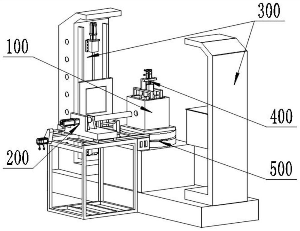
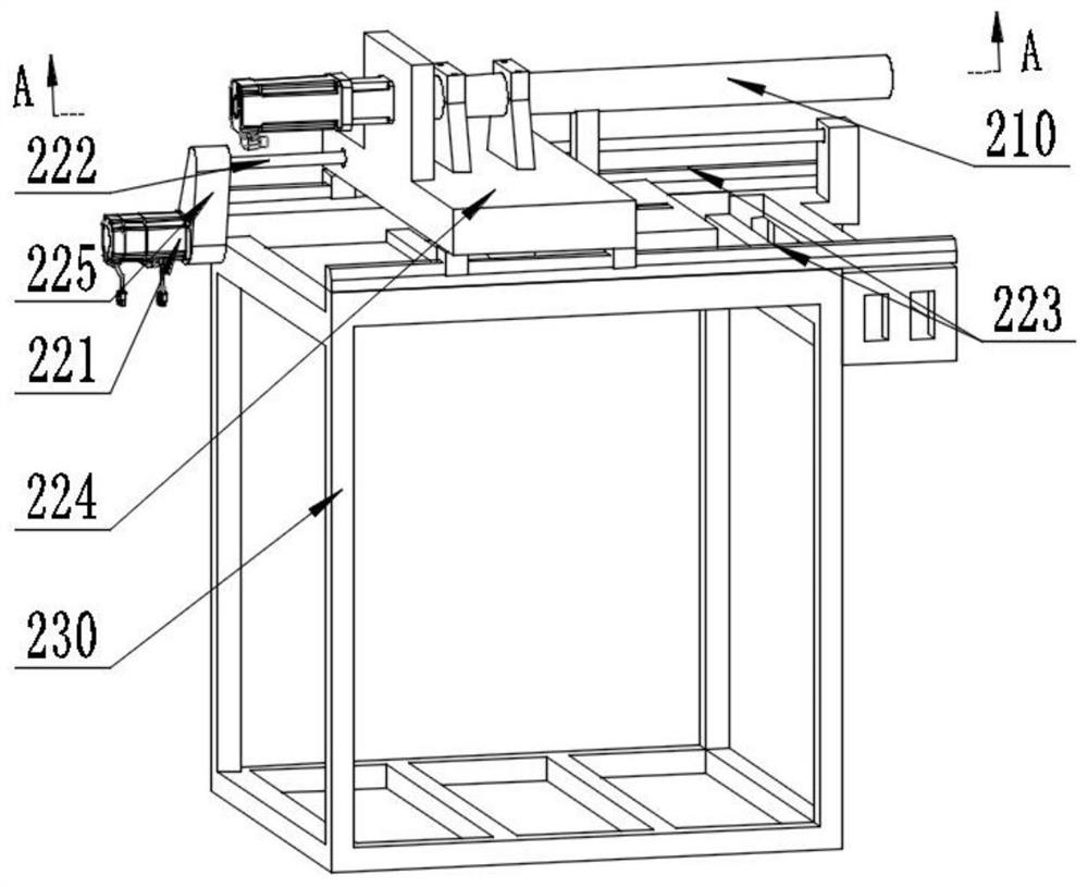
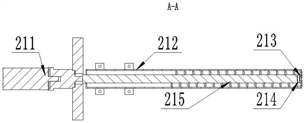
[0004] In order to solve the above-mentioned problems in the prior art, that is, in order to solve the problem that the real simulation of tunnel excavation and the visual detection of force deformation state cannot be realized in the test, the present invention provides a visualization device for simulating tunnel excavation, including a high-energy accelerator CT The scanning system, the turntable system and the tunnel model system are characterized in that they also include an excavation system and a vibration system, and the excavation system is used to simulate tunnel drilling; the excavation system includes a drilling device, a moving device and a supporting device , the drilling device is connected to the supporting device through a guide rail slider; the moving device is arranged on the supporting device, and is used to drive the drilling device close to or away from the tunnel model system;

Method used


Image

  • Visual device for simulating tunnel excavation
  • Visual device for simulating tunnel excavation
  • Visual device for simulating tunnel excavation

Examples


Embodiment Construction

[0030] Preferred embodiments of the present invention are described below with reference to the accompanying drawings. Those skilled in the art should understand that these embodiments are only used to explain the technical principle of the present invention, and are not intended to limit the protection scope of the present invention.

[0031] The invention provides a visualization device for simulating tunnel excavation, including a high-energy accelerator CT scanning system, a turntable system, a tunnel model system, an excavation system and a vibration system; wherein, the turntable system is used to carry the tunnel model system and can drive the tunnel The model is rotated; the high-energy accelerator CT scanning system combined with the rotating turntable system can perform a comprehensive three-dimensional scanning of the tunnel model to obtain a more accurate three-dimensional shape of the tunnel model internal changes; the excavation system is set in the tunnel model sy...


PUM


Abstract

The invention belongs to the technical field of tunnel engineering, discloses a visual device for simulating tunnel excavation, and aims to solve the problem that tunnel excavation real simulation andstress deformation state visual detection cannot be realized in a simulation test. The visual device comprises a high-energy accelerator CT scanning system, a turntable system, a tunnel model system,an excavation system and a vibration system. The vibration system is arranged on the upper side of the tunnel model system and is used for simulating construction blasting borne by tunnel surroundingrock or the seismic environment. Tunnel drilling is simulated through a drilling device arranged in the excavation system. A moving device arranged in the excavation system controls the propelling movement of the drilling device. The high-energy accelerator CT scanning system cooperates with the turntable system to achieve visual detection of stress deformation of the tunnel surrounding rock. According to the excavation system and the vibration system, tunnel excavation and stress deformation of the surrounding rock can be truly simulated, and the visual stress deformation state is obtained through the scanning system and the turntable system.

Description

technical field [0001] The invention belongs to the technical field of tunnel engineering, and in particular relates to a visualization device for simulating tunnel excavation. Background technique [0002] In recent years, with the large-scale development of my country's highways, railways, and subways, the proportion of tunnels in the line is getting higher and higher. Especially for the Sichuan-Tibet Railway, which has been under construction, the proportion of tunnels has reached more than 80%. Various problems in the process followed. During the tunnel construction process, the interaction between the cutter head of the roadheader (shield machine) and the rock and soil, the relationship between the rotation speed of the cutter head and the propulsion speed, and the torque of the cutter head, the stability of the tunnel excavation surface, the excavation process (blasting process and During an earthquake) surrounding rock stress, deformation, and damage are the key conce...

Claims


Application Information

Patent Timeline
IPC IPC(8): E21B47/002E21B47/06E21B3/02E21B15/00E21B17/22E21D9/08G01N23/046G01L5/00
CPCE21B3/02E21B15/003E21B17/22E21B47/06E21D9/08G01L5/0038G01N23/046
Inventor 毛天桥李晓李守定赫建明何鹏飞郑博张召彬李关访武艳芳
Owner INST OF GEOLOGY & GEOPHYSICS CHINESE ACAD OF SCI
Why Eureka
Eureka Blog
Learn More