
Electrode and ablation equipment

An electrode and electrode body technology, applied in the field of medical devices, can solve the problems of limited effect, high local field strength, and short operating distance, and achieve the effect of good effect, large electric field strength, and long operating distance.

Pending Publication Date: 2020-10-16
湖南菁益医疗科技有限公司
View PDF0 Cites 0 Cited by
  • Summary
  • Abstract
  • Description
  • Claims
  • Application Information

AI Technical Summary

Problems solved by technology

However, the electrodes in the prior art cannot generate high local field strength due to the use of elongated needle-shaped materials with smooth surfaces as electrodes, and there are problems of short action distance and limited effect when using the above-mentioned electrodes for treatment.

Method used


Image

  • Electrode and ablation equipment
  • Electrode and ablation equipment
  • Electrode and ablation equipment

Examples


Embodiment 1

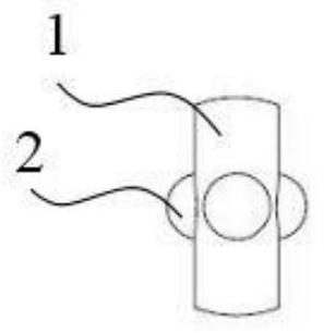
[0036] Such as Figure 1-3 , the electrode provided in this embodiment includes an electrode body 1 , a protrusion 2 and an electrode front end 3 . The electrode main body 1 is cylindrical, and a plurality of protrusions 2 are arranged in the axial and circumferential directions of the electrode main body 1 . Preferably, the protrusions 2 are arranged at equal intervals in the circumferential direction of the electrode body 1 , and the protrusions 2 are also arranged at equal intervals in the axial direction of the electrode body 1 . The electrode front end 3 is extended along one axial end of the electrode body 1, and the electrode front end 3 is reduced to a conical shape relative to the axis of the electrode body 1, forming a sharp needle point, which can achieve a better puncture effect.

[0037] The electrode provided in this embodiment is equivalent to setting a plurality of protrusions 2 on the smooth surface of the electrode body 1 . When a high-frequency current is ...

Embodiment 2

[0042] Such as Figure 4-5As shown, the electrode provided in this embodiment includes an electrode body 1 , a protruding ring 4 and an electrode front end 3 . The electrode main body 1 is cylindrical, and a plurality of protruding rings 4 are arranged at intervals in the axial direction of the electrode main body 1 . Preferably, a plurality of protruding rings 4 are arranged at equal intervals in the axial direction of the electrode body 1 . The electrode front end 3 extends along one axial end of the electrode body 1 , and the electrode front end 3 is reduced to a conical shape relative to the axis of the electrode body 1 , forming a sharp needle point.

[0043] The electrode provided in this embodiment is equivalent to setting a plurality of protruding rings 4 on the smooth surface of the electrode body 1 . When a high-frequency current is generated in the electrode, since the surface area of ​​the protruding ring 4 increases relative to the smooth surface, a skin effect ...


PUM


Abstract

The invention provides an electrode. The electrode comprises an electrode main body and an electrode front end, the electrode main body is a cylinder, micro convex parts are arranged on the electrodemain body, and the micro convex parts protrude out of the outer surface of the electrode main body; a plurality of micro convex parts are arranged at intervals along the axial direction of the electrode main body; and the front end of the electrode extends along the axis of the electrode main body, and the front end of the electrode is conical. The invention further provides ablation equipment. According to the electrode and the ablation equipment provided by the invention, the micro-convex structure is additionally arranged on the electrode main body with a smooth surface, and local high field intensity is formed on the micro-convex structure by utilizing the skin effect of high-frequency current; under the same electrode spacing, a discharge channel can be quickly established through local field enhancement, the cell breakdown probability is increased, and the requirement on external voltage amplitude is reduced; and under the same voltage level, the local field intensity can effectively increase the action distance between electrodes, and the actual application range is enlarged.

Description

technical field [0001] The invention belongs to the technical field of medical devices, and in particular relates to an electrode and ablation equipment, in particular to an electrode and ablation equipment for transient high-voltage interventional ablation. Background technique [0002] Malignant tumors are one of the major diseases that threaten human life and health. At present, the three conventional treatments of malignant tumors, surgery, chemotherapy, and radiotherapy, are far from being able to fully meet the needs of patients for prolonging survival and improving quality of life. Tumor treatment techniques are increasingly favored by clinicians. Minimally invasive interventional ablation therapy for tumors is considered to be another new type of effective therapy following surgery, chemotherapy, radiotherapy, and immunotherapy because of its obvious curative effect, less trauma, less toxic and side effects, fewer complications, and significantly shortened hospital s...

Claims


Application Information

Patent Timeline
IPC IPC(8): A61B18/12A61B18/14
CPCA61B18/12A61B18/1206A61B18/14A61B2018/00577A61B2018/1405A61B2018/1425
Inventor 李伟王全胜雷南林李泽中
Owner 湖南菁益医疗科技有限公司
Learn More