Automatic polishing resistance-trimming device for strain gauge

A strain gauge and resistance adjustment technology, which is applied in the direction of automatic grinding control devices, measuring devices, electromagnetic measuring devices, etc., can solve problems such as slow production efficiency, grinding omissions, and easy splashing of grinding fluid, so as to avoid splashing and reduce labor intensity , Improve the effect of grinding quality

Inactive Publication Date: 2020-10-16
厦门市诺盛测控技术有限公司
View PDF9 Cites 0 Cited by
  • Summary
  • Abstract
  • Description
  • Claims
  • Application Information

AI Technical Summary

Problems solved by technology

The resistance value of each strain gauge of the strain gauge array produced under the current manufacturing process cannot be precisely controlled, and the resistance value can only be adjusted to the required size through manual grinding or machine grinding in the later stage. The traditional manual grinding method Put a cotton swab on a small motor, dip it in a proper amount of polishing fluid, and then test and polish it on the test fixture with two probes. This manual operation method not only slows down the production efficiency, but also tends to cause shortcomings such as polishing omissions. Moreover, there will be residual cotton dust hanging on the wire grid during the grinding process, and the cleaning time will be increased in the subsequent cleaning process; the machine grinding method is to drive the grinding head to rotate through the motor, and the strain will be adjusted after the grinding head is dipped in the polishing liquid. The meter is rotated and polished. Due to the high rotation speed of the motor, the polishing fluid is easy to splash, and manual scrubbing is required after polishing.

Method used


Image

  • Automatic polishing resistance-trimming device for strain gauge
  • Automatic polishing resistance-trimming device for strain gauge
  • Automatic polishing resistance-trimming device for strain gauge

Examples


Embodiment Construction

[0043] In order to facilitate the understanding of those skilled in the art, the structure of the present invention will be further described in detail with reference to the accompanying drawings:

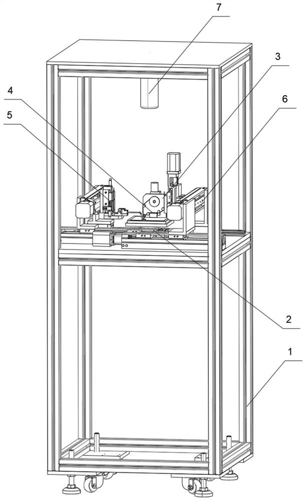
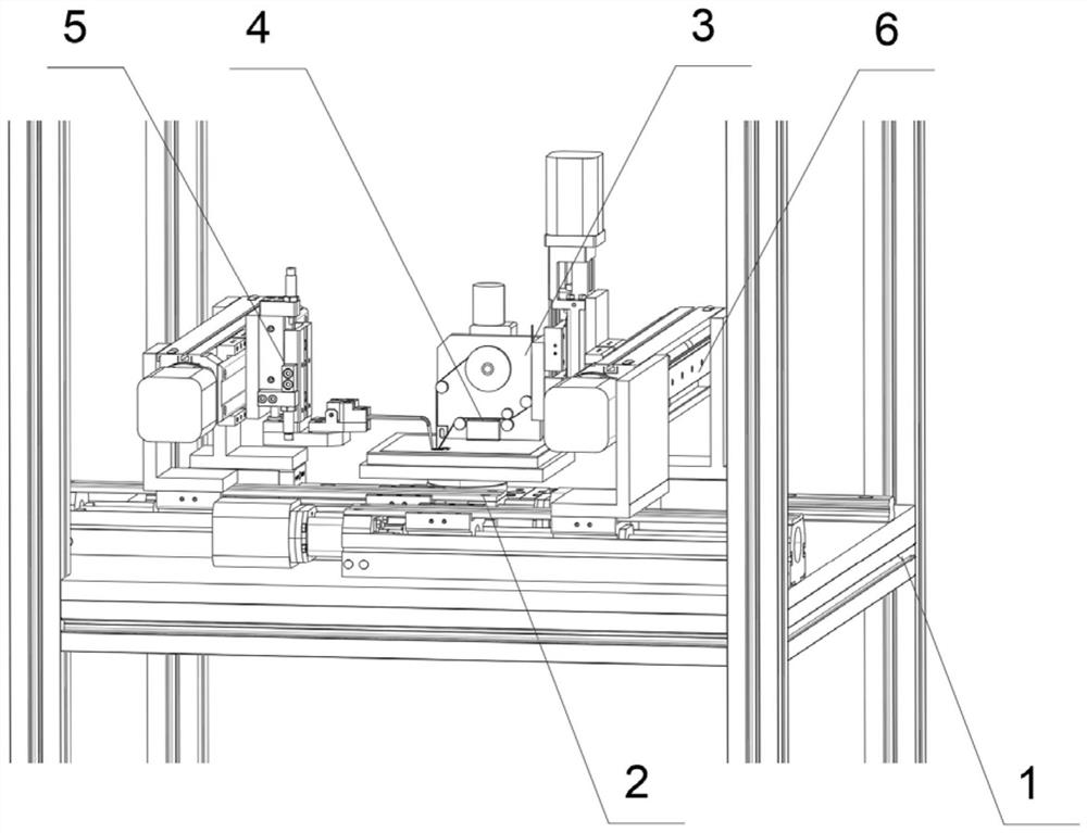
[0044] refer to Figure 1-8 , an automatic grinding resistance adjusting device for strain gauges, comprising a frame 1, and the frame 1 is provided with a workbench: it also includes:

[0045] The strain gauge array mounting base plate 2 is set on the workbench and used for placing the strain gauge array. The through hole is connected to the corresponding negative pressure generator for adsorbing the strain gauge array;

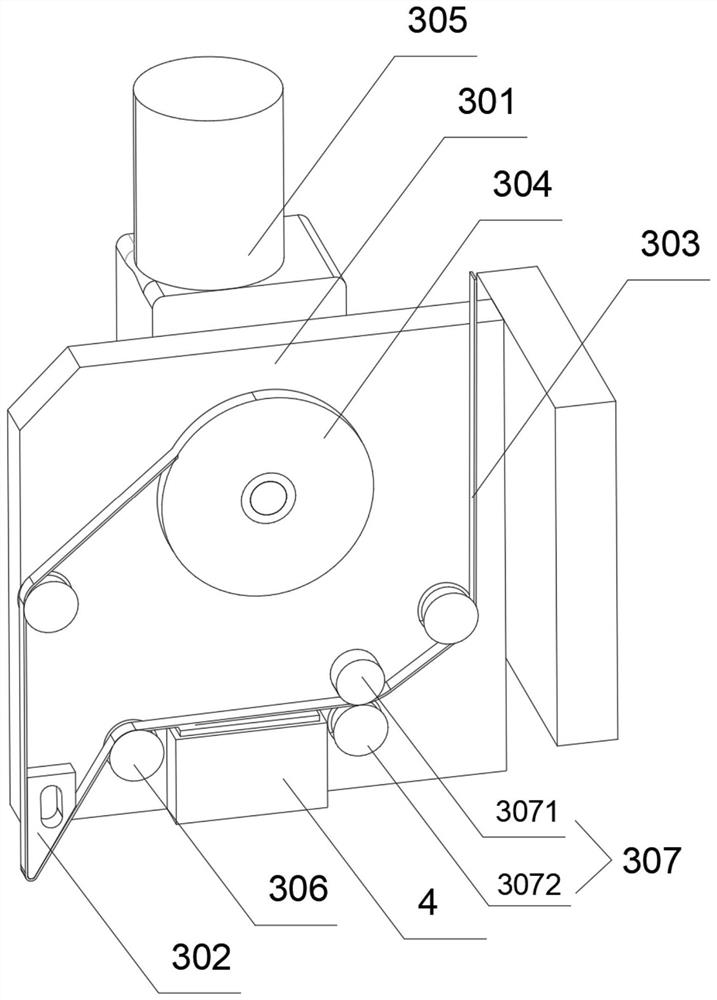
[0046]The sandpaper belt sanding mechanism 3 includes a sanding mechanism mounting plate 301, the sanding mechanism mounting plate 301 is provided with a sandpaper belt 303 and a sanding indenter 302, the tip of the sanding indenter 302 faces the strain gauge array mounting base plate 2, the The sandpaper belt 303 is output by the unwinding mechanism (not shown...


PUM


Abstract

The invention relates to an automatic polishing resistance-trimming device for a strain gauge. The automatic polishing resistance-trimming device comprises a frame, a strain gauge array mounting bottom plate, a sand-paper strip polishing mechanism, a polishing liquid output mechanism, a resistance measuring mechanism and a driving mechanism, wherein a workbench is arranged on the frame; the straingauge array mounting bottom plate is arranged on the workbench, and used for holding a strain gauge array; the sand-paper strip polishing mechanism comprises a polishing mechanism mounting plate; a sand-paper strip and a polishing pressure head are arranged on the polishing mechanism mounting plate; the tip of the polishing pressure head faces the strain gauge array mounting bottom plate; the sand-paper strip is output through an uncoiling mechanism, wound through the tip of the polishing pressure head, and recovered through a coiling mechanism finally; the coiling mechanism is driven througha corresponding motor; the polishing liquid output mechanism is arranged on the polishing mechanism mounting plate, and attached to the sand-paper strip between the uncoiling mechanism and the polishing head; the resistance measuring mechanism is used for getting in touch with the corresponding strain gauge and acquiring the resistance value of the strain gauge; and the driving mechanism is usedfor driving the sand-paper strip polishing mechanism or the resistance measuring mechanism to move.

Description

technical field [0001] The invention relates to the field of resistance regulating devices, in particular to an automatic grinding resistance regulating device for strain gauges. Background technique [0002] Strain gauge is a very widely used precision detection and perception unit in the field of processing and manufacturing today. It is widely used in physical quantity measurement, environmental quantity control, intelligent identification and other fields. refer to Figure 10 , The strain gauge is generally composed of sensitive grid, lead, adhesive, substrate and cover layer. [0003] During the production of strain gages, refer to Figure 9 , generally producing an array of strain gauge arrays. The resistance value of each strain gauge of the strain gauge array produced under the current manufacturing process cannot be accurately controlled, and the resistance value can only be adjusted to the required size by manual grinding or machine grinding in the later stage. T...

Claims


Application Information

Patent Timeline
Patent Type & Authority Applications(China)
IPC IPC(8): B24B21/00B24B21/18B24B21/20B24B57/02B24B51/00B24B49/12B24B49/00B24B41/06G01B7/16G01L1/22G01L9/04
CPCB24B21/004B24B21/18B24B21/20B24B41/06B24B49/00B24B49/12B24B51/00B24B57/02G01B7/18G01L1/22G01L9/04
Inventor 何志俊刘长俊潘成福
Owner 厦门市诺盛测控技术有限公司
Why Eureka
Try Eureka