
Ultrasonic shot blasting device for shaft parts

A shaft parts, ultrasonic shot peening technology, applied in the direction of abrasive feeding device, used abrasive processing device, abrasive jetting machine tools, etc., can solve the problem of inconsistent shot peening intensity on the upper and lower surfaces of shaft parts, and achieve improvement Shot peening efficiency and the effect of reducing energy loss

Active Publication Date: 2020-10-16
HUNAN UNIV OF SCI & TECH
View PDF5 Cites 6 Cited by
  • Summary
  • Abstract
  • Description
  • Claims
  • Application Information

AI Technical Summary

Problems solved by technology

[0005] The purpose of the present invention is to provide an ultrasonic shot peening device for shaft parts, which is used to solve the problem of inconsistent shot peening intensity on the upper and lower surfaces of shaft parts caused by the existing ultrasonic shot peening method

Method used


Image

  • Ultrasonic shot blasting device for shaft parts
  • Ultrasonic shot blasting device for shaft parts

Examples


Embodiment Construction

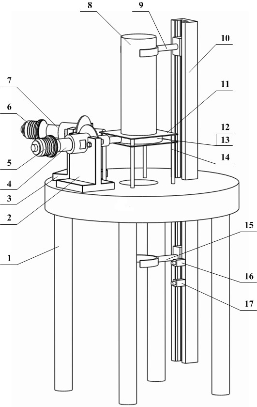
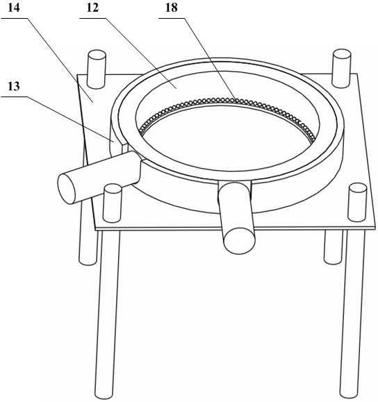
[0015] Below according to specific embodiment the present invention will be further described, see Figure 1~Figure 2 , an ultrasonic shot peening device for shaft parts, a workbench 1, an ultrasonic vibrating device, and a clamping device, is characterized in that the ultrasonic vibrating device consists of a transducer A5, a horn A4, a transducer B6, an amplitude Composed of rod B7 and circular tool head 12, the ultrasonic vibration head composed of transducer A5 and horn A4 is equal to the ultrasonic vibration head composed of transducer B6 and horn B7, with a phase difference of 90 degree, and one group of ultrasonic vibration heads produces radial vibration, and the other group produces bending vibration. The connection points of horn A4 and horn B7 on the ring tool head 12 differ by a quarter wavelength, and the ultrasonic vibration device passes The support A2 and the support B3 are installed on the workbench 1, and the workbench 1 is provided with a through hole, the d...


PUM


Abstract

The invention discloses an ultrasonic shot blasting device for shaft parts. The ultrasonic shot blasting device for the shaft parts comprises a workbench, an ultrasonic vibration device and a clampingdevice, and is characterized in that the ultrasonic vibration device consists of a transducer A, an amplitude-change pole A, a transducer B, an amplitude-change pole B and a circular tool head; the ultrasonic vibration device is mounted on the workbench through a support A and a support B; a through hole is formed in the workbench, a shot blasting chamber composed of a bottom plate, the annular tool head, an annular electromagnet and a top plate is arranged above the through hole, shots are placed in the shot blasting chamber, the shaft parts to be subjected to shot blasting are vertically placed through the clamping device and extend into the shot blasting chamber, and the clamping device is composed of a mechanical arm A, a mechanical arm B, a guide rail, a sensor A and a sensor B, thesensor A and the sensor B are mounted on the guide rail. According to the ultrasonic shot blasting device for the shaft parts, the annular tool head generates ultrasonic traveling waves under the combined action of two ultrasonic vibration heads, the shots are driven to conduct shot blasting treatment on the circumferential face of the shaft parts at the same time, and shot blasting uniformity isguaranteed.

Description

technical field [0001] The invention relates to the technical field of parts surface strengthening equipment, in particular to an ultrasonic shot peening device for shaft parts. Background technique [0002] Shot peening is a cold working surface modification and forming technology. Under the action of high-pressure wind or compressed air, the projectile hits the workpiece at a certain speed, causing elastic-plastic deformation of the material and forming pits on the metal surface, resulting in countless depressions. Overlap to form a uniform residual compressive stress layer. However, the impact force of traditional mechanical shot peening projectiles is limited, and the depth of residual stress produced by it is also limited, and the dents on the surface are relatively deep, resulting in increased metal surface roughness, and subsequent finishing processes need to be added to ensure the integrity of the parts roughness. In addition, dry shot peening is currently the most...

Claims


Application Information

Patent Timeline
Patent Type & Authority Applications(China)
IPC IPC(8): B24C1/10B24C3/04B24C3/32B24C7/00B24C9/00
CPCB24C1/10B24C3/04B24C3/32B24C7/00B24C9/00
Inventor 陈海锋胡宁陈权豪姜凌峰
Owner HUNAN UNIV OF SCI & TECH
Learn More