Control process of sulfide in sulfur bearing steel

A technology of sulfide and sulfur-containing steel, applied in the field of sulfide control technology in iron-based alloys, can solve problems such as unstable control and unsatisfactory effect, and achieve the effect of ensuring service performance and reducing adverse effects

Active Publication Date: 2020-10-16
JIANGYIN XINGCHENG SPECIAL STEEL WORKS CO LTD
View PDF6 Cites 0 Cited by
  • Summary
  • Abstract
  • Description
  • Claims
  • Application Information

AI Technical Summary

Problems solved by technology

At present, the methods for controlling the morphology of sulfide inclusions include calcium alloy, magnesium alloy, rare earth alloy, composite alloy denaturant and oxide metallurgy, etc., or the control is not stable, or the effect is not very satisfactory.

Method used


Image

  • Control process of sulfide in sulfur bearing steel
  • Control process of sulfide in sulfur bearing steel
  • Control process of sulfide in sulfur bearing steel

Examples


Embodiment 1

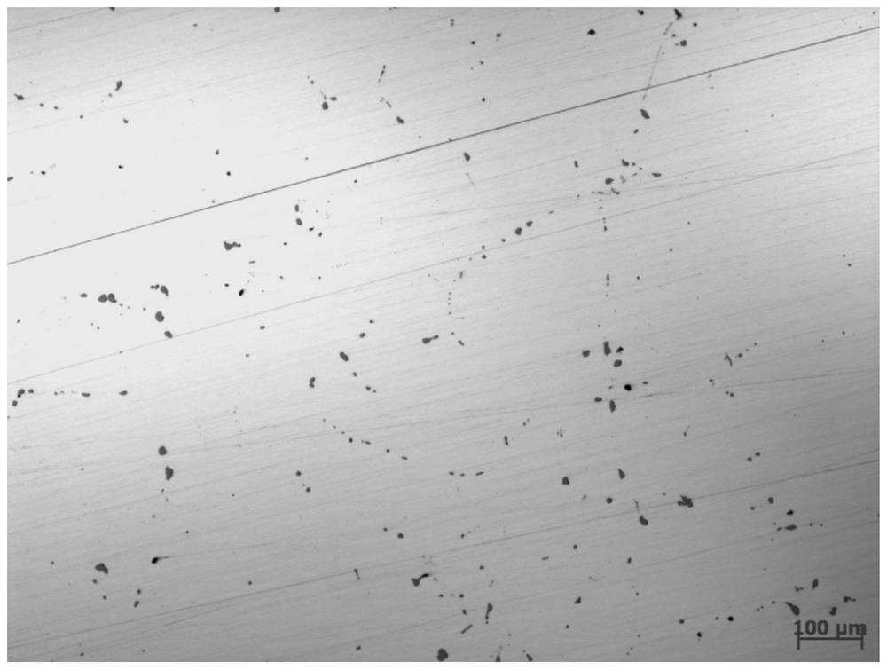
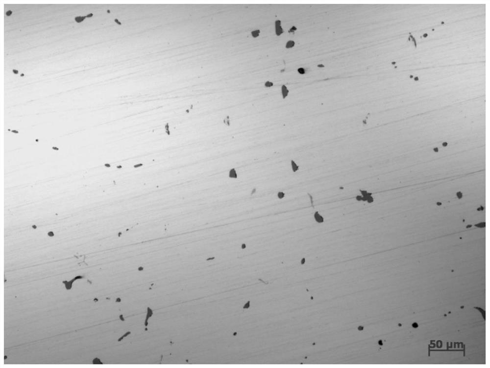
[0031] This embodiment relates to the production of a steel product with a sulfur content of 0.015%, and its chemical composition is calculated by mass percentage:

[0032] 0.47%C, 0.25%Si, 1.05%Mn, 0.009%P, 0.015%S, 0.08%Cr, 0.02%Ni, 0.07%Cu, 0.015%Al, 0.07%V, 0.002%Nb, 0.015%Ti, 0.01% Mo, 0.012% N, the balance is Fe and unavoidable impurity elements.

[0033] The manufacturing process of the 0.015% sulfur content steel product is: EAF electric furnace → LF refining furnace → VD vacuum refining furnace → molten steel denaturation treatment (adding 70m of composite cored wire whose main component is Fe-Mn-Ti-Zr, about 0.12Kg / tons of steel) → CCM continuous casting (M crystallizer + F end, M stirring frequency at 4Hz, stirring current at 100A, F stirring frequency at 20Hz, stirring current at 350A, where M is unidirectional rotation stirring, S+F is Forward / reverse two-way rotation stirring) EMS electromagnetic stirring continuous casting to obtain 300mm thick continuous ca...

Embodiment 2

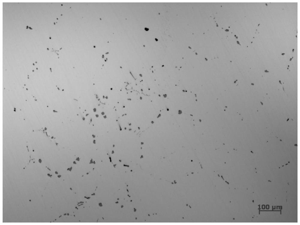
[0039] This embodiment relates to the production of a steel product with a sulfur content of 0.060%, and its chemical composition is calculated by mass percentage as:

[0040] 0.38%C, 0.58%Si, 1.45%Mn, 0.012%P, 0.060%S, 0.16%Cr, 0.01%Ni, 0.01%Cu, 0.015%Al, 0.0059%Ti, 0.01%Mo, 0.018%N, balance It is Fe and inevitable impurity elements.

[0041]The manufacturing process of the steel product with 0.060% sulfur content is: BOF electric furnace → LF refining furnace → RH vacuum refining furnace → molten steel denaturation treatment (adding 200m of composite cored wire mainly composed of Fe-Mn-Ti-Zr, about 0.36Kg / ton Steel) → CCM continuous casting (M crystallizer + S casting stream + F end, M stirring frequency at 2.5Hz, stirring current at 135A, S stirring frequency at 8.5Hz, stirring current at 240A, F stirring frequency at 18Hz, stirring The current is 350A, where M is one-way rotation stirring, S+F is forward / reverse two-way rotation stirring) EMS electromagnetic stirring cont...


PUM


Abstract

The invention relates to a control process of sulfide in sulfur bearing steel. The process comprises the steps that firstly, before pouring of molten steel, the molten steel is subjected to denaturating treatment, a main component of a denaturating agent is Fe-Mn-Ti-Zr, the agent is fed into the molten steel in a manner of a composite cored wire, the adding amount of the denaturating agent is calculated according to the Zr / S mass ratio being 0.014-0.018, and accordingly, a spindle and spherical compound vulcanized inclusion[Mn(Zr,Ti)S] with (Zr,Ti)S as a core and MnS as cladding and with ductility is formed; secondly, the molten steel is poured into a blank in a continuous casting manner, according to the content S of sulfur in the molten steel, one term or multiple terms of M crystallizerelectromagnetic stirring, S cast flow electromagnetic stirring and F end electromagnetic stirring are designed, in the continuous casting process, the compound sulfide is further broken under the different stirring forces, and the size can be further reduced and distributed; and thirdly, continuous casting blank hot rolling to form a product is carried out, and in the hot rolling process, it is ensured that the blank calendaring ratio is larger than or equal to 10:1. The vulcanized inclusion can be controlled to be in transverse dotted and longitudinal continuous strip distributed in the steel.

Description

technical field [0001] The present invention relates to a process for controlling sulfides in iron-based alloys. Background technique [0002] The continuous improvement of high speed, precision and automation in the machining of auto parts puts forward higher requirements on the machinability of materials. Sulfur-containing steel is widely used because of its excellent cutting performance. [0003] Sulfur mainly exists in the form of sulfide inclusions in steel. Since steel usually contains a certain amount of Mn element, Mn is the element with the strongest affinity with S, so S in steel often exists in the form of MnS, and the control of sulfide inclusions is also important. It is the control of MnS. Since MnS is a plastic inclusion, it can be deformed along with the steel matrix along the rolling direction in the subsequent rolling process to form strips and aggregate distribution. The banded MnS is more likely to separate from the matrix under the action of lateral fo...

Claims


Application Information

Patent Timeline
IPC IPC(8): C21C7/00C21C7/10C21D7/13B22D11/115C22C38/02C22C38/04C22C38/06C22C38/42C22C38/44C22C38/46C22C38/48C22C38/50
CPCC21C7/0056C21C7/0006C21C7/10B22D11/115C21D7/13C22C38/02C22C38/04C22C38/002C22C38/42C22C38/46C22C38/48C22C38/50C22C38/44C22C38/001C22C38/06
Inventor 刘乐东许晓红白云黄镇陈德
Owner JIANGYIN XINGCHENG SPECIAL STEEL WORKS CO LTD
Why Eureka
Try Eureka