Seabed in-situ monitoring buoy system, seabed in-situ monitoring system and seabed in-situ monitoring method

A monitoring system and buoy technology, applied in signal transmission system, closed-circuit television system, test water, etc., can solve the problems of unrealizable cost and transmission rate, high cost, low transmission rate, etc., and achieve long-distance communication and self-power supply. , The effect of reducing laying costs and expanding the scope of application

Pending Publication Date: 2020-10-16
YANTAI RENDA AUTOMATION EQUIP TECH
View PDF0 Cites 6 Cited by
  • Summary
  • Abstract
  • Description
  • Claims
  • Application Information

AI Technical Summary

Problems solved by technology

However, the existing water quality monitoring technologies have their own shortcomings. Among them, the use of water pumps or winches for water quality monitoring loses the meaning of in-situ measurement and data distortion; the use of regular manual sampling or regular floating to collect data is not only costly , and the timeliness of the data cannot be guaranteed; some profile monitoring equipment is used to lower the measurement part into the suspended water for measurement, and the stability of the test data cannot be guaranteed because the monitoring equipment swings with the ocean current
That is to say, the existing water quality monitoring equipment cannot realize the function of in-situ long-term online monitoring on the seabed, especially the long-term real-time online monitoring function of in-situ high-definition video on the seabed
[0004] In addition, in terms of data transmission, the current seabed in-situ monitoring system mostly uses 3G, GPRS, Beidou, or satellite data communication. Am

Method used


Image

  • Seabed in-situ monitoring buoy system, seabed in-situ monitoring system and seabed in-situ monitoring method
  • Seabed in-situ monitoring buoy system, seabed in-situ monitoring system and seabed in-situ monitoring method
  • Seabed in-situ monitoring buoy system, seabed in-situ monitoring system and seabed in-situ monitoring method

Examples


Embodiment approach

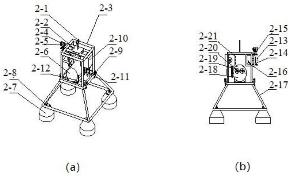
[0044] As a specific embodiment, the underwater fixing device includes an upper fixing box and a lower bracket, a water quality monitoring device and a video monitoring device are installed in the upper fixing box, the upper fixing box is connected with the lower bracket, and the lower bracket is fixedly connected with the seabed.

[0045] Specifically, the water quality monitoring device includes one or more sensors for monitoring water quality-related parameters; the video monitoring device includes an underwater high-definition camera for real-time shooting of high-definition video of the seabed environment; . The underwater fixing device provided by the invention can realize not moving with the water flow and not sinking, which provides a guarantee for the reliability and stability of the monitoring data.

[0046] As a preferred implementation manner, the video surveillance device further includes an LED supplementary light for supplementing light for video surveillance to...

Embodiment 1

[0051] This embodiment provides a buoy system for seabed in-situ monitoring, including a buoy device and an underwater fixing device.

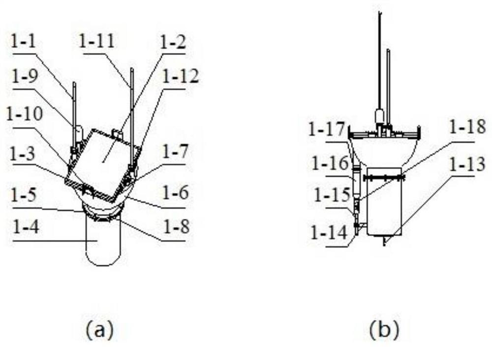
[0052] Among them, the buoy device as attached figure 1 As shown, it includes a communication antenna, a buoy upper barrel 1-6, a buoy lower barrel 1-4, and a solar panel 1-2. Specifically, the communication antenna includes a 5G antenna 1-1 and a data antenna 1-11, wherein the 5G antenna 1-1 is used for high-definition video communication, the data antenna 1-11 is used for general monitoring data communication, and the communication antenna is fixed through the antenna flange. 1-12 are fixedly installed on buoy upper barrel body 1-6; buoy upper barrel body 1-6 is equipped with a communication transmission control module, an energy-saving control module, a signal collection and processing module, and a buoy device monitoring module, which are respectively used for communication transmission control , energy-saving control, signal collection a...

Embodiment 2

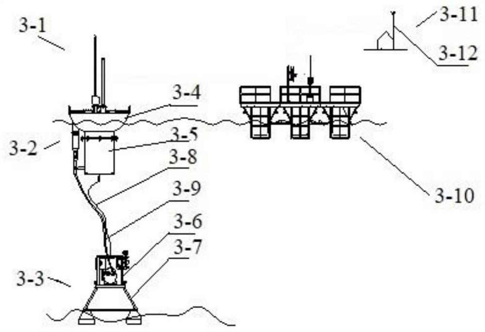
[0069] This embodiment provides a seabed in-situ monitoring system, as attached image 3 As shown, it includes a seabed in-situ monitoring buoy system 3-1, a sea-based floating platform 3-10, and a receiving shore station 3-11 (also called shore-based), wherein the seabed in-situ monitoring buoy system 3-1 includes a buoy device 3 -2 and the underwater fixing device 3-3, the buoy device 3-2 is connected with the underwater fixing device 3-3 through the cable 3-9 and the cable 3-8; the seabed in-situ monitoring buoy system 3-1 is connected with the sea-based floating platform Between 3-10, the sea-based floating platform 3-10 and the receiving shore station 3-11 are connected through wireless communication.

[0070] Specifically, the buoy device 3-2 includes a buoy upper barrel body 3-4 and a buoy lower barrel body 3-5; the underwater fixing device 3-3 includes an upper fixing box 3-6 and a lower bracket 3-7. The specific structures of the buoy device 3-2 and the underwater fi...


PUM


Abstract

The invention provides a seabed in-situ monitoring buoy system, a seabed in-situ monitoring system and a seabed in-situ monitoring method, and belongs to the field of marine environment monitoring. The seabed in-situ monitoring buoy system comprises a buoy device and an underwater fixing device. The buoy device comprises a communication antenna, a buoy upper barrel body and a buoy lower barrel body. The communication antenna is fixedly installed on the buoy upper barrel body, the buoy upper barrel body is connected with the buoy lower barrel body in a sealed mode, and the buoy device is connected with the underwater fixing device through a cable and a mooring rope. According to the seabed in-situ monitoring buoy system, real-time seabed in-situ high-definition video monitoring and water quality monitoring can be effectively achieved, in-situ high-definition video data and undisturbed in-situ water quality monitoring data can be transmitted to a receiving shore station in a low-cost mode under the severe sea condition, the laying cost is low, and the practicability is high.

Description

technical field [0001] The invention relates to the field of marine environment monitoring, in particular to a seabed in-situ monitoring buoy system, a seabed in-situ monitoring system and a seabed in-situ monitoring method. Background technique [0002] With the development of the marine economy, marine pastures and marine environmental monitoring have put forward higher requirements for marine intelligent monitoring, and the existing seabed in-situ monitoring system can no longer meet the requirements. [0003] In terms of water quality monitoring, the existing technology mostly adopts water pump or winch to realize water quality monitoring, or adopts regular manual sampling or regular floating to collect data to monitor water quality, or uses some profile monitoring equipment to lower the measuring part into suspended water for measurement To monitor water quality, etc. However, the existing water quality monitoring technologies have their own shortcomings. Among them, t...

Claims


Application Information

Patent Timeline
IPC IPC(8): G01C13/00G01N33/18G08C17/02H04N7/18B63B35/00
CPCB63B35/00G01C13/00G01N33/18G08C17/02H04N7/18
Inventor 吕荣福凌铁军马俊峰孙明卓屈厚余
Owner YANTAI RENDA AUTOMATION EQUIP TECH
Why Eureka
Try Eureka