
Novel mechanical control circuit and mode of frequency converter

A frequency converter, a new type of technology, applied in the direction of machine/engine, liquid variable capacity machinery, AC motor control, etc., can solve the problem that the frequency converter cannot detect the DC bus voltage machine control function, etc., to ensure the power supply capacity and service life. , easy to replace, improve the effect of system efficiency

Pending Publication Date: 2020-10-16
JIAXIPERA COMPRESSOR
View PDF5 Cites 1 Cited by
  • Summary
  • Abstract
  • Description
  • Claims
  • Application Information

AI Technical Summary

Problems solved by technology

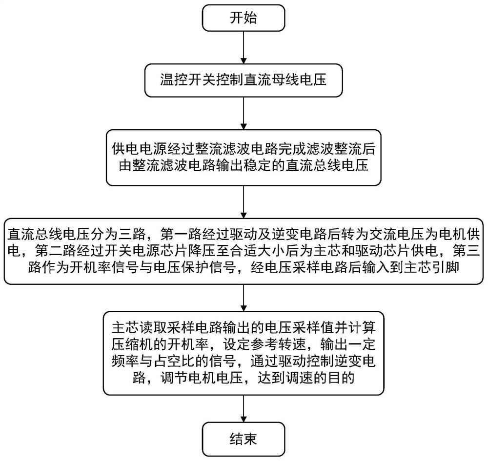
[0003] The present invention aims to overcome the problem that the frequency converter in the prior art cannot realize its machine control function by detecting the DC bus voltage, and provides a new type of machine control circuit and method of the frequency converter, which avoids additionally leading out the AC phase line as a control signal, and its DC The bus voltage is converted into high and low level signals that can be recognized by the microcontroller through a series of voltage division and filtering. Afterwards, the main core calculates the corresponding speed through the duty cycle of the signal and uses this as a reference to control the compressor.

Method used


Image

  • Novel mechanical control circuit and mode of frequency converter
  • Novel mechanical control circuit and mode of frequency converter

Examples


Embodiment Construction

[0030] The present invention will be further described below in conjunction with the accompanying drawings and specific embodiments.

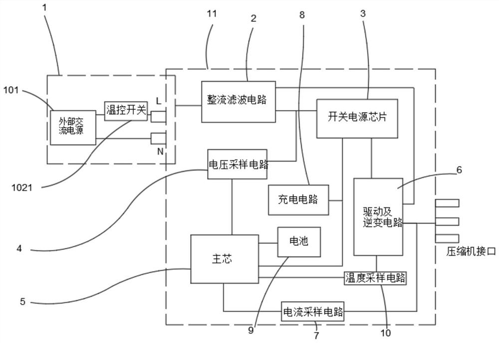
[0031] like figure 1 In the shown embodiment, it includes a power supply module 1 and a compressor module 11, the power supply module 1 is connected to the compressor module 11 to supply power for the compressor module 11, and the power supply module 1 includes an external AC power supply 101 for controlling the DC bus Voltage temperature control switch 102; the external AC power supply 101 includes two-phase output L phase and N phase, the connection terminals of the frequency converter include frequency converter connection terminal L and frequency converter connection terminal N, and the L phase circuit is connected in series with the temperature control switch 102 It is connected to the terminal L of the frequency converter, and the N-phase line is connected to the terminal N of the frequency converter. The temperature control switch 102 is...


PUM


Abstract

The invention discloses a novel mechanical control circuit and mode of a frequency converter, and aims to solve the problem that a frequency converter in the prior art cannot achieve the mechanical control function by detecting the voltage of a direct-current bus. The novel mechanical control circuit comprises a power supply module and a compressor module, wherein the power supply module is connected with the compressor module to supply power to the compressor module, the power supply module comprises an external alternating-current power supply and a temperature control switch used for controlling the voltage of a direct-current bus, and the compressor module comprises a whole filter circuit, a switching power supply chip, a voltage sampling circuit, a main core, a driving and inverting circuit, a current sampling circuit, a charging circuit, a battery and temperature sampling circuit and a power supply module. According to the invention, an alternating current phase line is preventedfrom being additionally led out to serve as a control signal, a direct current bus voltage is converted into a high-low level signal which can be recognized by a single chip microcomputer through a series of voltage division and filtering, and a main core calculates the corresponding rotating speed according to the duty ratio of the signal and controls a compressor with the corresponding rotatingspeed as reference, so that the cost is reduced; and the problem of over-high cost caused by additionally arranging a battery and a charging circuit is solved.

Description

technical field [0001] The invention relates to the field of frequency conversion control of compressors, in particular to a novel machine control circuit and method of a high-performance and low-cost frequency converter. Background technique [0002] With the development of frequency conversion technology, frequency conversion compressors have received great attention and widespread attention in the field of refrigeration appliances due to their advantages in energy saving, high efficiency and performance. The frequency converter is the core of the frequency conversion compressor, and many different signal control methods have been derived in the process, such as: mechanical control, electronic control, UART protocol, AC protocol, etc. Among them, the main features of machine-controlled frequency converters are: low replacement cost, no need for main control board signal control, and easy maintenance. These characteristics make it show unique advantages in the process of g...

Claims


Application Information

Patent Timeline
IPC IPC(8): H02P27/06F04B37/12F04B49/06H02J9/06
CPCH02P27/06F04B49/06F04B37/12H02J9/06H02J9/061
Inventor 邹文忠黄弘历胡菲凡张兵李琛超陈乐玲
Owner JIAXIPERA COMPRESSOR
Learn More